


Pratt & Whitney Rzeszów S.A.
MAINTENANCE MANUAL
PZL-10W ENGINE
1992.08.28
80-02-00
Page 407
Export Control Classification: PL/UE 9E999
B.
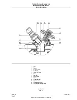
Installation of claw coupling.
(1 )
Fix splines (38a) of torsional shaft (38) in the fixture (see 72-02-00, Table 2 0 1 , item 7).
(2)
Place shim (37) and driven half-coupling (27) on torsional shaft (38).
(3)
Measure clearance "L" between inner surface of driven half-coupling (27) and face of torsional
shaft (38), which should be 0,4÷ 0,8 mm (.016 in. ÷ 0.32 in.).
NOTE:
In the case when measured clearance
“
L" is different than required, adjust it by
selection of appropriate shim (37) (see 72-02-00, Table 203, item 46).
(4)
Install a new lock (36) (see 72-02-00, Table 203, item 45) so that bosses of lock come into slots
on face of torsional shaft (38) and then washer (35) and screw (34).
(5)
Screw initially screw (34) by torque wrench (see 72-02-00, Table 201, item 10, 12) with torque of
21,6 Nm (2,2 kGm; 191 lb.in.) and then unscrew it and again screw it home applying the torque
of 11,8 14,7 Nm (1,2 kGm - 1,5 kGm; 104 lb.in. - 130 lb. in.).
(6)
Secure screw (34) by bending the flange of lock (36) in three points on circumference.
(7)
Place assemblied torsional shaft assembly (38) with mounted driven half- coupling (27) into front
case (39).
NOTE:
Torsional shaft (38) has also internal splines cut on external splines surface (invisible
on Dwg. 403), so when putting torsional shaft assembly (38) into inlet case (39), its
angular position should be found in such a way, in which it may by placed in its place
without resistance.
(8)
Place washers (40) on screws (41 ) and tighten up torsional shaft assembly (38) by torque
wrench (see 72-02-00, Table 201, item 10, 1 3) applying torque 9,8 ÷ 1 1 , 8 Nm (1 ÷1 , 2 kGm;
8 7
÷
1 0 4 Lb.in.).
Then wire secure screws (41 ).
(9)
Perform installation of driving half-coupling according to item 1 .B.