


NOVA electronics Inc. MCX514 -
120
-
120
-
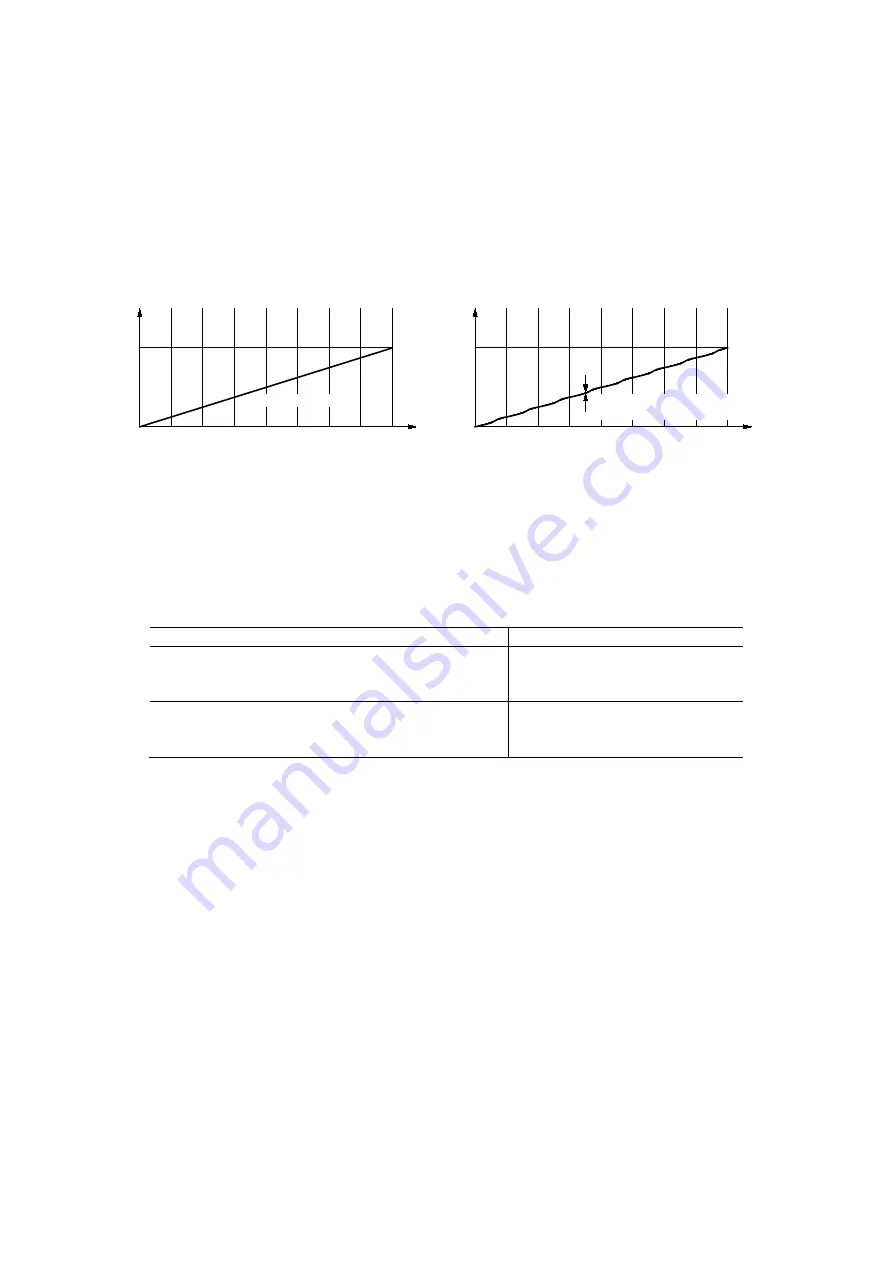
3.3.8 Position Drift in Helical Interpolation
Helical interpolation performs circular interpolation in the XY plane, and moves Z or U axis in synchronization with the circular
interpolation. Ideally, the increased amount of the rotation angle in the center of circular interpolation must be directly
proportional to the increased amount of Z/U axis feed as shown in Fig. 3.3-5. However, as the circular interpolation in MCX514 is
performed in the XY orthogonal coordinates, the increased amount of output pulses in X and Y axes is not directly proportional to
the increased amount of the rotation angle in the center of circular interpolation. This affects the Z/U axis feed that is calculated by
output pulses from X and Y axes of circular interpolation, as a result, it is not also directly proportional. Each time the quadrant
changes in circular interpolation, periodic drift is generated.
0°
90
180
270
360
Rotation Angle (degree) in XY Circular Interpolation
Feed
Amount
Z- axis
Displacement
45
135
225
315
0°
90
180
270
360
Rotation Angle (degree) in XY Circular Interpolation
Z /U- axis
Displacement
45
135
225
315
Drift range
:
±0
.
1% or less
(when feed amount of Z/U- axis is 100%)
Drift range
:
0%
Feed
Amount
Fig. 3.3-5 Ideal Z-axis Feed in Helical Interpolation
Fig. 3.3-6 MCX514 Z/U axis Drift in Helical Interpolation
As shown in Fig. 3.3-6, the position of Z or U axis is, each time the quadrant changes in circular interpolation, periodic drift is
generated. The drift range from an ideal position depends on operation environment and as follows.
Table 3.3-6 Drift Range of Feed Amount from Ideal Position
Operating Condition
Drift Range from Ideal Position
Short axis pulse equalization mode
+
2-axis high accuracy constant vector speed mode
±0.1
%
or less
Without both
Short axis pulse equalization and
constant vector speed mode
±0.4
%
or less
For more details of short axis pulse equalization mode, see chapter 3.6.
For more details of constant vector speed mode, see chapter 3.5.


