


NOVA electronics Inc.
MCX514 -
103
-
103
-
■
Manual pulsar mode
Set D9, 8 bits of PIO signal setting 2
・
Other settings (22h) to 1, 1 and set the appropriate speed parameters for driving and drive
pulse number. Connect the A-phase signal of an encoder to nEXPP input and the B-phase signal to nEXPM input. When nEXPM
signal is on the Low level,
+
direction relative position driving is activated at the rising edge
↑ of nEXPP signal. When nEXPM
signal is on the Hi level,
-
direction relative position driving is activated at the rising edge
↑ of nEXPP signal. When the drive
pulse number is set to 1, one drive pulse is output at the each rising edge
↑ of nEXPP signal. If drive pulse number is set to TP, the
TP number of drive pulses is output.
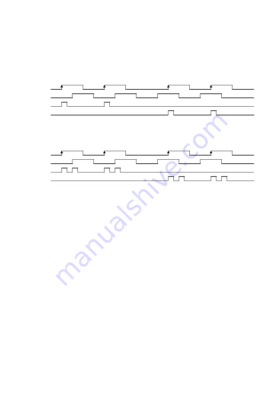
XEXPP
(A-phase)
XEXPM
(B-phase)
XPP
XPM
Normal rotation
Reverse rotation
Fig. 2.12-3 Example of X axis Driving (Drive Pulse Number: 1) by Manual pulsar
Normal rotation
Reverse rotation
XEXPP
(A-phase)
XEXPM
(B-phase)
XPP
XPM
Fig. 2.12-4 Example of X axis Driving (Drive Pulse Number: 2) by Manual pulsar
Set the speed parameter in the following conditions to complete output of the TP number of drive pulses with a period from the
rising edge
↑ of nEXPP signal to the next rising edge ↑ of nEXPP signal.
DV
≧
F×TP×2
DV
:
Drive speed (pps)
TP
:
Drive pulse number
F
:
Frequency (Hz) at the maximum speed of the manual pulsar encoder
For instance, under the conditions where the maximum frequency of the manual pulsar is F=500Hz and the drive pulse number is
TP =1, the drive speed must be DV=1000pps or greater. Since acceleration/deceleration driving is not applied, set the initial speed
SV to the value larger than the drive speed DV. However, when a stepping motor is used for driving, the drive speed must not
exceed the self-starting frequency of the motor.


