1-24
Equipment operation
Nortel Networks Confidential
411-2051-500
Draft
00.01
November 1999
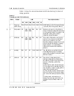
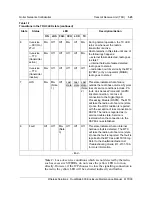
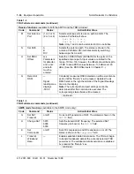
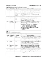
Table 1-1 shows the various transitions in LED state that may be observed
during operation.
Table 1-1
Transitions in the TRU3 LED state
State
Status
LED
Description/Action
ON
LOS FAIL CCH LCR
TX
1
Power-up
(LED check)
Flash Flash Flash Flash Flash Flash
LEDs flash on and off for approximately
1 second, then radio goes to state 2.
2
Diagnostics Off
Last
state
Last
state
On
On
Off
Radio is not in service. It performs a
series of hardware diagnostic tests that
run for approximately 12 seconds. If all
tests pass, radio goes to state 3;
otherwise, it goes to state 5.
3
ROM-idle
On
Last
state
Last
state
On
On
Off
If the radio in this state is not put into
service in one minute, it resets itself
and returns to state 2. The radio
transitions between states 2 and 3 until
it is put into service (state 6), loading
begins (state 4), or a Hard Reset
command is received from the MTX
(state 2).
4
Loading
On
Off
Off
Flash Flash
Off
The ON LED is on and the CCH and
LCR LEDs flash during the loading
period. When loading is complete, radio
returns to state 2.
5
Idle fault
Off
Off
On
Off
Off
Off
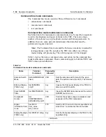
The radio is in this state when a
hardware diagnostic test fails before
the radio is put into service. When the
radio is in this state, perform the
following:
(a) Re-seat the radio into its slot again
(or to another slot) to identify if the fail
was caused by a power supply glitch or
some other transient event.
(b) If the fault is cleared, the FAIL LED
turns off, the ON, CCH and LCR LEDs
turn on and the radio proceeds to state
2.
(c) If the FAULT LED remains on,
replace the radio and return it to your
Customer Service Office (CSO) for
repair.
- continued -
Содержание DualMode 800
Страница 2: ......
Страница 4: ......
Страница 6: ...vi Publication history Nortel Networks Confidential 411 2051 500 Draft 00 01 November 1999...
Страница 82: ...2 20 Periodic maintenance 411 2051 500 Draft 00 01 November 1999...
Страница 90: ...3 8 Test equipment and precautions 411 2051 500 Draft 00 01 November 1999...
Страница 100: ...5 6 Master Oscillator tests 411 2051 500 Draft 00 01 November 1999...
Страница 106: ...6 6 Antenna and transmission line tests 411 2051 500 Draft 00 01 November 1999...
Страница 116: ...8 4 Alarm Control Unit ACU tests 411 2051 500 Draft 00 01 November 1999...
Страница 138: ...10 2 ICRM tests 411 2051 500 Draft 00 01 November 1999...
Страница 200: ...12 10 Enclosure maintenance 411 2051 500 Draft 00 01 November 1999...
Страница 208: ...A 8 Appendix A Frequency table 411 2051 500 Draft 00 01 November 1999...
Страница 215: ......

