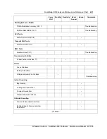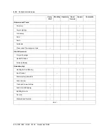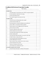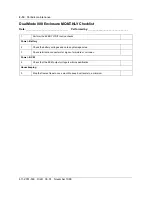
Outside grounding
2-5
Wireless Solutions
DualMode 800 Enclosure
Maintenance Manual
MTX08
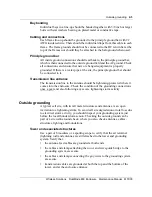
Bay bonding
Individual bays in a line-up should be bonded together with 3/8 inch or larger
bolts with star washers bearing on plated metal or conductive tape.
Cabling and connections
Each frame line-up should be grounded to the principle ground bar with #2
AWG insulated wire. There should be individual drops from this cable to each
frame. The frame grounds should not be connected to the DC return bar at the
top of the frames nor should they be attached to the halo ground when used.
Principle ground bar
All inside ground connections should lead back to the principle ground bar,
which is then connected to the outside ground field and the AC ground. Check
all connections and ensure that new or changed equipment is properly
grounded. If there is a water pipe at the site, the principle ground bar should
be connected to it.
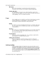
Transmission line entrance
The transmission line to the antenna should be lightening-protected where it
comes into the enclosure. Check the condition of the grounding connections
once a year and also following any severe lightening storm activity.
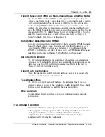
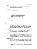
Outside grounding
A typical cell site, with its tall metal structures and antennas, is an open
invitation to a lightening strike. To avoid cell site degradation or total loss due
to electrical storm activity, you should inspect your grounding system just
before the local thunderstorm season. Checking the outside ground can be
part of a site walk-around check, where you also check antennas, cables,
structures, lighting and foundations.
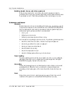
Tower and associated structures
Use a pair of binoculars or a spotting scope to verify that the air terminal
(lightning rod) and antennas are still attached to the tower and grounding
system. Verify that:
•
the antenna feed cables are grounded at both ends
•
the cables and clamps attaching the tower and waveguide bridge to the
grounding system are secure
•
the cables and clamps connecting the guy wires to the grounding system
are secure
•
transmission cables are grounded at both the top and the bottom of the
tower, and at the enclosure entrance
Содержание DualMode 800
Страница 2: ......
Страница 4: ......
Страница 6: ...vi Publication history Nortel Networks Confidential 411 2051 500 Draft 00 01 November 1999...
Страница 82: ...2 20 Periodic maintenance 411 2051 500 Draft 00 01 November 1999...
Страница 90: ...3 8 Test equipment and precautions 411 2051 500 Draft 00 01 November 1999...
Страница 100: ...5 6 Master Oscillator tests 411 2051 500 Draft 00 01 November 1999...
Страница 106: ...6 6 Antenna and transmission line tests 411 2051 500 Draft 00 01 November 1999...
Страница 116: ...8 4 Alarm Control Unit ACU tests 411 2051 500 Draft 00 01 November 1999...
Страница 138: ...10 2 ICRM tests 411 2051 500 Draft 00 01 November 1999...
Страница 200: ...12 10 Enclosure maintenance 411 2051 500 Draft 00 01 November 1999...
Страница 208: ...A 8 Appendix A Frequency table 411 2051 500 Draft 00 01 November 1999...
Страница 215: ......

