background image

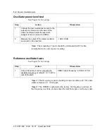
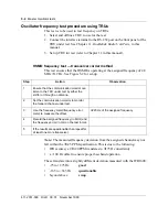
Reference oscillator tests

5-3

Wireless Solutions

DualMode 800 Enclosure

Maintenance Manual

MTX08

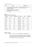
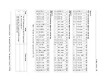
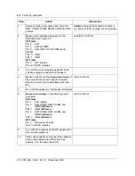
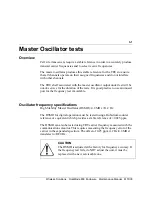
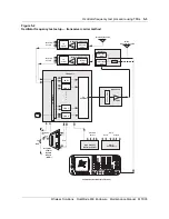
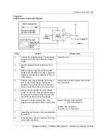
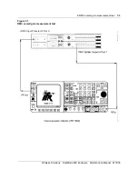
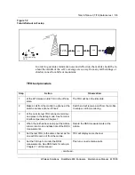
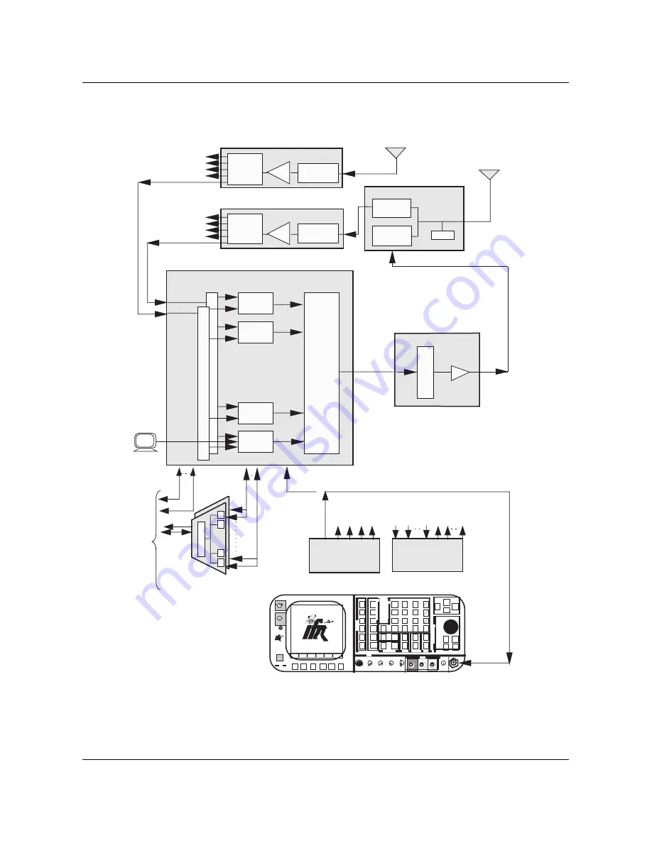
Figure 5-1
Oscillator power level and frequency test setup

Diversity Receive

Main

Transmit / Receive

MCPAs

TRU Shelf

Other TRU

Shelves

Other TRU

Shelves

LNA

Preselect

Filter

Receive Multicoupler

1:8 Splitters

1:8

Splitter

LNA

Duplexer

RX Bandpass

Filter

TX Bandpass

Filter

TRU 8

TRU 2

TRU 7

TRU 1

1:8

Splitter

Preselect

Filter

Receive Multicoupler

Integrated

Cellular
Remote

Module

(ICRM)

Data

L

I

N

K

P

P

P

To

MTX

Voice

P

Alarm

Inputs               Outputs

Other TRU

Shelves

Alarm

Control Unit

High Stability 

MasterOscillator

Data

••••  •  •

••••  •  •

Communications Monitor (IFR 1600)

INTENSIT

Y

POWER

DUPLEX

OUT

O N

F1

F2

F3

F4

F6

F5

MODE

ANTENNA

F M / A M   1 6 0 0 S

AUX

IN

FM/AM

1600S

65W 
MAX

65W 
MAX

A P P L I E D

RF

RCVR

DPLX

AF

SCOPE

MTRS

AUTO

SGL

GO

STOP

PRINT

HOLD

SETUP

STORE

0

CE

DEL

8

5

2

SHIFT

RCL

7

4

1

#

^

v

9

6

3

Enter

^

v

+

-

M

u

k

m

.

TESTCONTROL

DATAENTRY

MEMORY

EDIT

SQLCH

VOL

FIELD

SELECT

^

v

<

>

^

v

<

>

MIC/ACC

SINAD

AUDIO

DEMOD

V

COM

AMP

SCOPE

T/R

IN/OUT

IN

IN

OUT

OUT

1KVDC/500V

AC MAX

2 AMPS 

MAX

IN

200 VDC 

MAX

200W
MAX

IN/OUT

BER

DMM

DATASCROLL

EXT MOD

STEP

SCRN

SCRN

GEN

GEN

ANLZ

Sniffer

VT100

4:1 Combiner

MCPA Shelf

Tx

Combiner

Содержание DualMode 800

Страница 1: ...Wireless Solutions DualMode 800 Enclosure Maintenance Manual MTX08 Draft 00 01 November 1999 DRAFT 411 2051 500...

Страница 2: ......

Страница 3: ...re it uses to protect its own confidential information but with no less than reasonable care Except as expressly authorized in writing by Nortel Networks the holder is granted no rights to use the inf...

Страница 4: ......

Страница 5: ...Nortel Networks Confidential v Wireless Solutions DualMode 800 Enclosure Maintenance Manual MTX08 Publication history October 1999 Draft 00 01 Draft issue of document for internal review...

Страница 6: ...vi Publication history Nortel Networks Confidential 411 2051 500 Draft 00 01 November 1999...

Страница 7: ...nsmit Receive Unit TRU 1 22 The front panel display interface 1 22 The Terminal Interface 1 26 Fullscreen commands 1 31 Command line mode commands 1 36 Multi Channel Power Amplifier MCPA 1 43 Installi...

Страница 8: ...ance 2 7 Fringe coverage 2 7 Handoff checks 2 7 Antenna sweep 2 7 Housekeeping 2 8 Heating air conditioning 2 8 Dust control 2 8 Statutory requirements 2 8 Site licenses 2 8 Trash and loose articles 2...

Страница 9: ...return loss 6 2 Antenna return loss test 6 2 Thruline wattmeter method Antenna return loss 6 4 Antenna sweep 6 4 Enhanced Receive Multicoupler ERMC tests 7 1 ERMC description 7 1 ERMC overall gain me...

Страница 10: ...audio line sensitivity test 11 25 Receive audio level test 11 26 RSSI test 11 27 RSSI offset calibration 11 29 SAT detect test 11 35 ST detect test 11 36 Setting RX audio level to site operational lev...

Страница 11: ...l layout of the TRU3 2 23 Figure 2 8 Fullscreen display for the TRU2 2 29 Figure 2 9 Fullscreen display for the TRU3 2 30 Figure 2 10 Selection menu for the MCPA 2 44 Figure 2 11 Power setting menu fo...

Страница 12: ...of power cables 4 2 Table 4 2 RIP1 circuit breaker assignments and ratings 4 3 Table 4 3 RIP2 circuit breaker assignments and ratings 4 3 Table 4 4 RIP3 circuit breaker assignments and ratings 4 3 Tab...

Страница 13: ...nical reference foundation for the other documents in the documentation suite and is written for all The Pre Installation Guidelines provides information on site selection concrete pad preparation and...

Страница 14: ...n Organization of this document This publication is organized to present the following information overview of the TDMA 800 MHz Universal Enclosure highlighting the components layout of the equipment...

Страница 15: ...cess to the ACU MPU board You can use this interface to configure and monitor the alarm input points and the control output contacts To access the ACU for local maintenance and monitoring you need a V...

Страница 16: ...t 00 01 November 1999 Figure 1 1 ACU Initial screen display You can choose one of the four primary options at the first level Input Output General Analog Ins not used Each option consists of up to thr...

Страница 17: ...n example to select the other options Note The left and right arrow keys move the cursor to options on the same line The up arrow key moves the cursor back to the previous line and the down arrow key...

Страница 18: ...keys to move the cursor from one parameter to another parameter 6 Press the Return key a second time to execute the selected parameter of the option The display will show Command Sent Acknowledge Rec...

Страница 19: ...44 to 248 Reserved For the assignment of the external input alarm points refer to Table 3 7 in the DualMode 800 Enclosure Functional Description 411 2051 100 The status of each point is displayed as f...

Страница 20: ...the RETURN key Enable Single The Enable Single function enables input alarm points one at a time You must enable an input alarm point before it will report alarm conditions to the MTX Disable Single...

Страница 21: ...ACU clock display The display updates the time once every minute The status of each point is displayed as follows see Figure 1 4 for the screen display Open The output contact is open Closed The outpu...

Страница 22: ...a time Close Range The Close Range function closes a group of output contact points at a time General option You can select the following four functions under the General option Set Clock Restart Sho...

Страница 23: ...ne In directed mode the DCSM performs test functions under the control of the MTX When you power up or reset a DCSM the DCSM performs a self test Note During power up it may take as long as four minut...

Страница 24: ...em will not recognize the mobile unit or allow it to function unless the programming on the Numerical Assignment Modules NAM is completed The Hughes M6200 handset NT3P75AB The Hughes M6200 cellular te...

Страница 25: ...Digital indicates that the current call is in digital mode Up Down Volume Adjusts the keypad speaker and earpiece sound Control keys level This key is also used to scroll through the parameters of th...

Страница 26: ...be programmed when the DCSM is installed in the cell site The NAM parameters that can be programmed are Area Code Phone Number Access Overload Class ACCOLC Primary 1st Paging Channel 1STCHP1 Secondary...

Страница 27: ...igit security code The factory default security code is 000000 When the correct security code is entered the display shows the ESN of the mobile telephone Record the ESN number as it is required for d...

Страница 28: ...even digit phone number Use the arrow key to scroll to the Access Overload Class ACCOLC display Enter the ACCOLC The default setting is 10 for the DCSM For NAM4 only Use the arrow key to scroll to the...

Страница 29: ...for bench testing to prevent interference with local cel1site CCHs 333 for A or 334 for B system Use the arrow key to scroll to the Secondary First Paging Channel 1STCHP2 display Enter the three digi...

Страница 30: ...ults Note These fields define the control channels the DCSM is to use For example range of control channels STCHAx DCCS 1 and or 1STCHBx DCCS 1 For NAM4 only Use the arrow key to scroll to the DCCHS n...

Страница 31: ...d Repeat this step for the other Extended System IDs Ex SID2 Ex SID8 Use the arrow key to scroll to the Unlock Code display Enter your four digit Unlock Code The factory default is 0000 Note Nortel Ne...

Страница 32: ...l Indicator display Dig Ind Note In the DCSM applications always enter a 1 to allow the mobile to indicate if it is in Digital mode Use the arrow key to scroll to the Sticky Analog display StickyA Not...

Страница 33: ...eset the unit You can also perform a BSY and RTS to reset the DCSM You have programmed NAM s non volatile memory when the self test is completed NAM 4 must be programmed as well if only one telephone...

Страница 34: ...the system selection options When the system of your service area appears consistent with your Primary First Paging Channel 1STCHP1 in NAM4 stop scrolling Press the STO key to confirm your selection...

Страница 35: ...When the phone rings lift the handset from the hang up cradle and press the SND key to answer the call Note If the phone is locked or you are accessing functions or storing recalling a number when the...

Страница 36: ...ing functions The operating parameters and status information on the front panel display are also available through the terminal interface by using the QUERY FAULT command in the command line mode Thi...

Страница 37: ...igital Locate Receiver The next character on shows an asterisk if the TRU is currently transmitting Otherwise it is left blank The last four characters show the current channel number or if the TRU is...

Страница 38: ...one minute it resets itself and returns to state 2 The radio transitions between states 2 and 3 until it is put into service state 6 loading begins state 4 or a Hard Reset command is received from th...

Страница 39: ...n In service TTC transmitter inactive On Off Off Off Off Off 7 LOS On On Note 1 Off Last state Last state Last state Note 2 This state indicates that a failure outside the radio has occurred Typical l...

Страница 40: ...re entered by way of a VT100 or compatible terminal connected to the RS 232 interface on the front panel of the TRU This allows maintenance test query and measurement functions to be performed without...

Страница 41: ...Fullscreen Monitor is intended for use on a DRU not in an active call processing state Note The TRU3 does not support AMPS mode However the commands for AMPS operation can still be entered in both th...

Страница 42: ...Table 1 3 Table 1 4 to Table 1 6 show and explain the command line mode commands The terminal screen is divided horizontally into a status area and a command area The bottom line of the terminal displ...

Страница 43: ...TRU display B Set Channel H Change SAT N Set Path T Set Audio Sens C PA on off I Tone Gen O Set RSSI Offset U Set TXPOWSTEP D PA LED on off J Loopback P Detect SAT ST RSSI X Exit E Set TXPOWIDX K Comp...

Страница 44: ...t Audio Sens B Set Channel H Change SAT N Set Path U Set TXPOWSTEP C PA on off I Tone Gen O Set RSSI Offset X Exit D PA LED on off J Loopback P Detect SAT ST RSSI Y Restart TRU E Set TXPOWIDX K Compan...

Страница 45: ...ar on the message line Enter the appropriate parameter and press the Return key to execute the command Only one command may be executed at a time Table 1 2 TRU Fullscreen command summary Code AMPS Mod...

Страница 46: ...plays and the Synth Lock field displays NO D Set PA LED on off Turns the alarm LED on the front panel of the MCPA on or off The status is shown in the PA Alarm field I Set Tone Gen BCH RF Off Turns on...

Страница 47: ...0 unless otherwise specified as a site requirement F Set MAXTXPOW 1 0 dBm to 27 0 dBm Note These values are for NO PATYPE used in Urban Defines the maximum power level dBm which maps to an Attenuation...

Страница 48: ...between 130 dBm and 30 dBm See the RSSI Offset tests in Chapter 11 Q Detect All RSSI Signal reading area displays 000 0 Constantly measures RSSI detected on all the six antenna ports until the Return...

Страница 49: ...x 10 0 dBm RX Sens 28 0 dBm xx x 16 0 dBm Note Set both TX and RX Sens to 18 0 in the tests described in this manual TDMA mode functions available to the TDMA mode only Code Command Status Action Init...

Страница 50: ...me command state and action for the command line mode maintenance commands These commands apply to both the TRU2 and TRU3 unless stated otherwise Table 1 4 Command line mode maintenance commands Name...

Страница 51: ...he LAPD timeout If the TRU detects loss of the LAPD link it resets itself after 10 12 seconds With the LAPD timeout set off the TRU does not reset which is necessary for stand alone testing Message In...

Страница 52: ...PATH A B CURRENT DIV VCH Set the diversity receiver to be either the A 0 or B 1 path or enable diversity switching 2 Receive SAT Color Code Set RXSATCC detector cc VCH Configures the SAT detector to...

Страница 53: ...hat corresponds to a dBm power level Set PA Power Step Set TXPOWSTEP dB_adjustment VCH CCH or TTC Adjusts the output power DPC stepsize of the MCPA by the amount specified The power step value can be...

Страница 54: ...rsity port or the channel number and RSSI readings from each port Digital Verification Color Code Query DVCC TTC The DVCC status for each slot In TRU3 the status indicates the actual SAT value Display...

Страница 55: ...display on the TRU2 Reset reason Query RESETREASON Any When the DRU is reset a reason code is stored in a reserved area of memory and can be read when the DRU is active again to give the reason for t...

Страница 56: ...Sanity Tests For TRU2 only TEST EEPROM Any Calibration information is stored in EEPROM along with an associated CRC This test calculates each table s CRC and compares to the stored CRC If a table has...

Страница 57: ...ep is required only if you are upgrading the firmware to a newer version 4 enter the per channel output power and the number of channels for the MCPA shelf 5 initialize the power setting Installing th...

Страница 58: ...the Comm Port COMM1 2 3 or 4 parameter to match the physically connected serial communications port on the computer Note To verify communications between the computer and the MCPA shelf check for a te...

Страница 59: ...n and using the comm port that the MCPA software is trying to use If a Run time error message appears every time you try to run the software use the following procedure to fix the problem 1 Use the Wi...

Страница 60: ...the Running the MCPA software on the computer section The power setting menu will pop out see Figure 1 11 2 At the menu click on the Download parameter and then select the software version for example...

Страница 61: ...ower remains at 2 5 watts while the total MCPA output power is reduced to 30 watts 12 channels x 2 5 watts In this case you do not need to set the power level again if the per channel output power is...

Страница 62: ...that all carriers are on will appear Make sure that the number of turned on carriers TRUs matches the number of channels entered Click OK 5 At the Initialization Done prompt click OK Power set up is c...

Страница 63: ...ow you to recognize deteriorating performance by comparing current and past test results ensure that all steps required to protect equipment have been taken create a maintenance history of a cell site...

Страница 64: ...33 41 26 31 32 49 50 55 56 40 57 65 64 72 48 9 17 2 7 8 16 24 4 5 1 8 TRU Shelf1 TRU Shelf2 TRU Shelf3 TRU Shelf4 TRU Shelf5 TRU Shelf6 TRU Shelf7 TRU Shelf8 TRU Shelf9 MCPA1 MCPA2 MCPA3 MCPA4 MCPA5...

Страница 65: ...HSMO in an all analog cell site will show up in the TRU transmit frequency tests Refer to the tests in Chapter 5 HSMO Tests in this manual Alarm Control Unit ACU The ACU alarm input points for equipm...

Страница 66: ...rocedures refer to manufacturer s recommendation Rectifiers The rectifiers used in the DualMode 800 Enclosure are virtually maintenance free For information refer to the DualMode 800 Enclosure Functio...

Страница 67: ...the antenna should be lightening protected where it comes into the enclosure Check the condition of the grounding connections once a year and also following any severe lightening storm activity Outsid...

Страница 68: ...binoculars or a spotting scope if necessary To perform a partial inspection check the tower base for cracks concrete break up and upheaval check all guy anchors for cracks or upheaval check guy tensio...

Страница 69: ...rmance should be tested once a year and can be gauged by the following tests It should be taken into consideration that coverage and handoffs can be impacted by seasons and weather Fringe coverage Usi...

Страница 70: ...siness licenses are often required to operate a cell site It may be worth your while to check up on these once a year to ensure that they are being maintained whether they are located on the site or w...

Страница 71: ...ntenance schedules for the different sites should be staggered so that labour time is more effectively and efficiently managed Table 2 1 shows an example of a maintenance schedule for six cell sites w...

Страница 72: ...og Receive Sensitivity Ch 11 Receive Audio Level Ch 11 RSSI Curve Ch 11 SAT Detect Ch 11 ST Detect Ch 11 Audio Loopback Ch 11 TRU Transmit Tests Analog PA Carrier Power Level Ch 11 Transceiver Carrier...

Страница 73: ...Path Tests Insertion Loss Ch 11 RMC Tests Insertion Loss Ch 7 Troubleshooting Transmission Facilities Copper Audio Link voice T1 Power Fuses Breakers Battery Rectifiers Voltage and polarity on the bay...

Страница 74: ...s Pressurized Transmission Lines Site Performance Fringe Coverage Handoff Checks Antenna Sweep Housekeeping Heating Air Conditioning Dust Control Statutory Requirements Site Licenses Trash and Loose A...

Страница 75: ...est 8 Check air filters on air exchange conditioner equipment 9 Verify the presence of a fire extinguisher check expiry date 10 Check for leaks in the shields 11 Check the condition around the enclosu...

Страница 76: ..._________________________ 1 Perform the EVERY VISIT routine checks Power Battery 2 Check the battery voltages and note any discrepancies 3 Check terminals connectors for signs of moisture or corrosion...

Страница 77: ...te ____________________________ Performed by ___________________________ 1 Perform the EVERY VISIT routine checks 2 Perform the MONTHLY routine checks Equipment bay 3 Voltage and Polarity checks at Ma...

Страница 78: ...1 November 1999 DualMode 800 Enclosure SEMI ANNUAL Checklist Date ____________________________ Performed by ___________________________ 1 Perform the EVERY VISIT routine checks 2 Perform the MONTHLY r...

Страница 79: ...ions on the rectifiers by adjusting the high and low voltage Inside grounding 10 Check that each bay line up is grounded to the principle ground bar with 2 AWG insulated wire and individual drops from...

Страница 80: ...onents for rust 28 Check for flaking paint often a sign of over stress 29 Check the over all condition of the paint re paint if necessary 30 Check that the transmission line is adequately supported an...

Страница 81: ...37 Check for insects mouse and birds nest in intake and exhaust systems 38 Inspect temperature in all equipment bays Licenses and other requirements 39 If the building uses AC mains service from overh...

Страница 82: ...2 20 Periodic maintenance 411 2051 500 Draft 00 01 November 1999...

Страница 83: ...ment are required This chapter provides a list of recommended test equipment and precautions to be aware of when performing any tasks at the cell site Test equipment It is assumed that the operator is...

Страница 84: ...5 meter N male to N male RF Cables 6 Two 1 5 meter N male to BNC male RF Cables 7 Two 1 5 meter BNC male to BNC male RF cables 8 Narda 370BNN 50 ohm Terminations 9 Bird 8325 Coaxial Attenuator 500 Wat...

Страница 85: ...the ICRM and the test equipment should be powered up for at least half an hour before the tests Inaccurate measurements may result if the warm up period is less than 30 minutes Test equipment Proper...

Страница 86: ...egrated Circuits ICs boards assembled with these devices Identification Manufacturers vary in their methods of identifying static sensitive equipment They may apply stickers or mark components with va...

Страница 87: ...table mats Where protective measures have not been installed a suitable alternative would be the use of a Portable Field Service Grounding Kit 3M part number 8012 This consists of a portable mat and w...

Страница 88: ...ts protective package except in a static free location The recommended packaging is a form of Faraday cage that will protect the contents against any charge present under normal conditions Damaged pac...

Страница 89: ...ircuit boards and components in proper protective packages during storage Discard suspect bags and use new ones Whenever possible units requiring protection should be identified on the protective pack...

Страница 90: ...3 8 Test equipment and precautions 411 2051 500 Draft 00 01 November 1999...

Страница 91: ...is either removed or replaced If the voltage or polarity of the DC power is incorrect equipment damage may result DC power inspection An orderly installation of DC power is required at the enclosure...

Страница 92: ...ndicated on the labels Note See Tables 5 12 to 5 4 for the RIP breaker panel assignments 5 Verify that the equipment bays are bonded to the principle ground bar line up feeder with a 6 AWG jumper Tabl...

Страница 93: ...20 21 22 23 24 MCPA 2 1 TRU 4A TRU 5A TRU 6A Not used Not used Not used Not used Not used Not used LVD 2A TCU 2A TCU 2B LVD 2B Not used Not used Not used Not used IM Light Bay 2 Light TRU 6B TRU 5B TR...

Страница 94: ...ent and the RIP breakers 6 Measure and record the Voltage and Polarity of the power terminals with respect to the DC Return bar at the top of each frame CE and RF 26 5 to 29 Vdc 7 Turn ON the breakers...

Страница 95: ...on of the tests It is good practice to use an unused port for the frequency test if available Oscillator frequency specifications High Stability Master Oscillator HSMO 4 8 MHz 1 2 Hz The HSMO for digi...

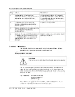
Страница 96: ...te 2 The HSMO is adjusted at the factory for frequency accuracy If the frequency test fails do not adjust the unit but replace with a new unit Step Action Observation 1 Connect the communications moni...

Страница 97: ...K P P P To MTX Voice P Alarm Inputs Outputs Other TRU Shelves Alarm Control Unit High Stability MasterOscillator Data Communications Monitor IFR 1600 INTENSIT Y POWER DUPLEX OUT O N F1 F2 F3 F4 F6 F5...

Страница 98: ...ssigned channel may not fall within the 0 25 PPM specification This is due to the following IFR accuracy at 0 20 PPM translates to 175 Hz uncertainty a 100 Hz offset to ensure proper baseband operatio...

Страница 99: ...ata L I N K P P P To MTX Voice P Alarm Inputs Outputs Other TRU Shelves Alarm Control Unit High Stability MasterOscillator Data Communications Monitor IFR 1600 INTENSIT Y POWER DUPLEX OUT O N F1 F2 F3...

Страница 100: ...5 6 Master Oscillator tests 411 2051 500 Draft 00 01 November 1999...

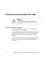
Страница 101: ...ine shield Of course the antenna must be electrically connected to the coaxial transmission line but most important the transmission line shield must be grounded for lightning protection The other DC...

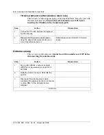
Страница 102: ...attmeter Method section Step Action Observation 1 Visually inspect the bonding of the transmission line to the mast ground riser at both the top and bottom of the tower The transmission line must be b...

Страница 103: ...nation to the open port on the VSWR bridge and step the generator through the receive and transmit band to verify the test set up for return loss Return loss should be greater than 35 dB over the band...

Страница 104: ...s are OFF before disconnecting the antenna cable Step Action Observation 1 Connect the Thruline between the duplexer and the antenna 2 Measure the forward and reverse power using the appropriate eleme...

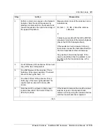
Страница 105: ...to the main transmission line and resweep It is possible to have a bad jumper If the result s are still bad then the problem could be either with the transmission line or the antenna 5 Do a TDR sweep...

Страница 106: ...6 6 Antenna and transmission line tests 411 2051 500 Draft 00 01 November 1999...

Страница 107: ...test is required for a cell site suspected of faulty operation The test is service affecting Step Action Observation 1 Notify the Control Center to OFFLINE the cell site 2 Disconnect the antenna feed...

Страница 108: ...MHz 7 Using the communication monitor in spectrum analyzer mode sweep the RMC and note any irregularities in the gain Gain measured may vary depending on cell site requirements for RF sensitivity ver...

Страница 109: ...ERMC overall gain measurement test 7 3 Wireless Solutions DualMode 800 Enclosure Maintenance Manual MTX08 Figure 7 1 RMC overall gain measurement test RMC Input Preselect Filter A...

Страница 110: ...are tuned correctly If they are not the user could get noisy channels usually due to co channel interference low RF levels or both This usually happens to sites with large coverage where the multicou...

Страница 111: ...one at the switch and leave phone off hook Switch end will receive a call from the mobile to setup a call for monitoring 3 At the cell site test TRU connect a terminal and place in the debug mode See...

Страница 112: ...t be equal to or stronger than the Talk In path If there are significant differences in the Talk out base TX levels on different antennas check for a defective RF component such as an antenna a cable...

Страница 113: ...change the status of any output control contact For a complete description of the ACU refer to the DualMode 800 Enclosure Functional Description 411 2051 100 Alarm Control Unit test setup Connect a VT...

Страница 114: ...alarm records See Chapter 1 Equipment operation for a description of all the menus 4 Test all equipped alarm points on the ACU This can be done by performing action such as turning DC breaker OFF remo...

Страница 115: ...m Control Unit test setup 8 3 Wireless Solutions DualMode 800 Enclosure Maintenance Manual MTX08 Figure 8 2 shows the pin assignments of a typical alarm connector Figure 8 2 Typical alarm connector 36...

Страница 116: ...8 4 Alarm Control Unit ACU tests 411 2051 500 Draft 00 01 November 1999...

Страница 117: ...l Channel CCH and Voice Channels VCH of a cell site can be verified to be operating correctly Stand alone mode tests In stand alone mode the mobile unit in the DCSM functions in the same manner as a s...

Страница 118: ...incoming call but will not generate a tone or loop the forward and reverse audio paths Nortel Networks recommends that the MRLT MRHT MRLP and MRLR VCH tests be used for verifying the performance of a...

Страница 119: ...M as unsolicited messages When MON is ON the ICP periodic audit process entails commanding the DCSM to monitor the current CCH in sequence Once the DCSM mobile is locked onto the CCH the ICP commands...

Страница 120: ...on in which the DCCH ACCH serves The following tests are available from the MTX MAP position CCH MAP level forward DCCH ACCH RF power measurement POWER reverse DCCH ACCH RF power measurement RSSI ACCH...

Страница 121: ...al post the DCSM by entering MAPCI MTC MTX CELL cell_number CTU POST DCSM_number 2 Make sure that the posted DCSM is in the INSV in service state If not place the DCSM to the INSV state by entering BS...

Страница 122: ...the TX power of the DCSMs page response RECC or RACH The readings are in a raw format and are translated into dBm at the CM Procedure 9 4 is used to test the reverse power Procedure 9 3 Measuring for...

Страница 123: ...dure 9 5 Round Robin Monitoring Step Action Observation 1 Make sure that the DCCH or ACCH and the DCSM have been posted and are in the INSV state as per the Control Channel Test Setup Procedure 2 If t...

Страница 124: ...er the Control Channel Test Setup Procedure 2 At the ACCH level of the MAP position enter TST CCHOMT 3 The system responds by displaying the information on the MAP terminal Check the log values report...

Страница 125: ...l MTX trunk tests use a four letter acronym to describe the functionality of the test Each letter of the test acronym is explained in Table 9 1 MTX Audio Low Test and MTX Audio High Test MALT MAHT Thi...

Страница 126: ...s measured by the TTT The TTT also makes a measurement of the noise level accompanying the audio signal at the return end of the loop The MALT and MAHT tests do not use the DCSM as part of the test pa...

Страница 127: ...MAP level of the MTX radio VCH to be tested example MAPCI MTC MTX CELL 100 VCH 2 Post the radio to be tested example POST 2 3 Invoke the MALT MAHT test on the posted radio TST MALT or TST MAHT The MT...

Страница 128: ...rameters of the circuit the Loop Loss the Loop Noise the Path Far to Near Loss The MRLT and MRHT tests can be invoked in the following ways from a posted transceiver at the VCH MAP levels from the CTT...

Страница 129: ...ing the MRLT and MRHT tests Procedure 9 9 Initiating the MRLT MRHT tests Step Action Observation 1 Go to the MAP level of the MTX radio VCH to be tested example MAPCI MTC MTX CELL 100 VCH 2 Post the r...

Страница 130: ...the test still fail the following hardware components may be at fault TRU CCH or VCH related Power Amplifier s Combiner ICRM packs the AX50s AX47s AX87s T1 transmission equipment used ICP cards the A...

Страница 131: ...then transmits a tone level and frequency determined in Table CTTPARMS which is transmitted on the forward RF path by the DUT to the DCSM The DCSM subsequently loops the forward audio to the reverse...

Страница 132: ...PWR The measured forward RF power in dBm Troubleshooting action If the test fails then it should be repeated for verification Should the test still fail the following hardware components may be at fa...

Страница 133: ...to the DCSM mobile The DCSM then transmits a 1004 Hz tone at 2 9 kHz deviation for five seconds after which the FWD audio is looped to the REV audio The TTT then transmits a tone level and frequency d...

Страница 134: ...dure 9 11 Initiating the MRLR test Step Action Observation 1 Go to the MAP level of the MTX radio VCH to be tested example MAPCI MTC MTX CELL 100 VCH 2 Post the radio to be tested example POST 2 3 Inv...

Страница 135: ...time with known good units and the test repeated When the test passes the faulty unit may have been found MTX Call Processing Mobile Termination Test MTRM or DTRM For this test the DCSM is used to ter...

Страница 136: ...ing the DCCH of the partition and the VCH are posted the Call Termination test may be performed Procedure 9 12 Invoking the DTRM or MTRM tests Step Action Observation 1 At the VCH MAP level enter TST...

Страница 137: ...Enclosure Maintenance Manual MTX08 ICRM tests 10 There are no operational tests for the Integrated Cellular Remote Module ICRM at the cell site If you want to check the operation of the ICRM contact t...

Страница 138: ...10 2 ICRM tests 411 2051 500 Draft 00 01 November 1999...

Страница 139: ...ogy greatly reduces maintenance requirements Due to functions being performed by software code rather than circuits composed of discrete elements that cause drift over time and with temperature change...

Страница 140: ...s 411 2051 500 Draft 00 01 November 1999 Figure 11 1 Front panel layout of the TRU2 NTAX98AA Figure 11 2 Front panel layout of the TRU3 NTAW99AA RS 232 port for the Terminal Interface connector Handle...

Страница 141: ...and routes the control and voice signals to the ICRM Audio sensitivity of the TRU In AMPS mode as a speaker talks the FM carrier varies as a function of the audio waveform produced by the speaker s v...

Страница 142: ...exer Digital tests the bit error rate loopback test checks that the transmit and receive paths of the TRU meet the specifications A digital call through test checks that TDMA call processing is perfor...

Страница 143: ...sure that all test equipment is calibrated before use Cable loss must be accounted for in the MCPA RF output power tests For a list of the required test equipment refer to Chapter 3 Test Equipment and...

Страница 144: ...If the check fails replace the TRU 5 Disconnect the interface terminal from the TRU under test DRU configurations for analog tests The Transmit Receive Unit TRU must be correctly configured for each t...

Страница 145: ...terface terminal For each individual test change the specific configuration s as required Table 11 1 shows the TRU configurations in the initial setup and in the individual tests Status or values in b...

Страница 146: ...OFF OFF OFF OFF OFF OFF OFF OFF OFF OFF OFF OFF OFF OFF OFF OFF RSSI SAT ST OFF OFF OFF A A A A A A A A A A A A A A A A A A A A 1 4 1 4 1 4 1 4 1 4 1 4 1 4 1 4 1 4 1 4 1 4 1 4 1 4 1 4 1 4 1 4 1 4 1 4...

Страница 147: ...en field on the screen should show Tone Gen off Antenna Path If the Antenna Path status is not Path A select Path A by entering N The TRU will request an antenna path choice either A B or DIV To selec...

Страница 148: ...er step size 1 4 in 0 25 dB increments To set power step size to 4 enter 4 The TxPwrStep field on the screen should show TxPwrStep 4 Maximum Transmit Power If the PA Max power status is not 15 0 dBm s...

Страница 149: ...pond as follows Enter TX or RX and a decimal dBm value TX 28 10 RX 28 16 Enter TX 18 0 The Audio Sens TX status on the screen will show Audio Sens Tx 18 0 RX Audio Sensitivity If the RX Audio Sens sta...

Страница 150: ...r test However the measurement may not be as accurate because the level is approximately 50 dB down with a tolerance of up to 5 dB Transmit test setup procedure 1 At the MTX busy and off line the TRU...

Страница 151: ...e channel assigned to the TRU under test by using the B command B The TRU will request a channel number Enter the channel number for the frequency assigned to the TRU under test 1 799 or 990 1023 Refe...

Страница 152: ...Inputs Outputs Other TRU Shelves Alarm Control Unit High Stability MasterOscillator Data Communications Monitor IFR 1600 INTENSIT Y POWER DUPLEX OUT O N F1 F2 F3 F4 F6 F5 MODE ANTENNA F M A M 1 6 0 0...

Страница 153: ...REQ ERR is also shown on some communications monitors 220 Hz of the assigned frequency 3 Record the assigned frequency in MHz and the frequency error in Hz on the test forms Step Action Observation 1...

Страница 154: ...4 Check the SAT carrier frequency deviation as displayed on the deviation DEV meter Deviation between 1 8 kHz and 2 2 kHz 5 Record the frequency and the deviation on the test forms 6 Use the H comman...

Страница 155: ...sure that the TRU configurations are as listed in Table 11 1 for the Residual Modulation test 2 Check the carrier frequency deviation as displayed on the DEV meter Deviation between 0 5 kHz and 0 5 kH...

Страница 156: ...cate the tone generated and the level of the tone 5 Check the carrier frequency deviation as displayed on the DEV meter Deviation between 2 61 kHz and 3 19 kHz 6 Record the deviation on the test forms...

Страница 157: ...Carrier Frequency Deviation for each of the levels listed TGEN 1004 100 TGEN 1004 50 TGEN 1004 0 TGEN 1004 10 TGEN 1004 20 TGEN 1004 30 TGEN 1004 50 The Carrier Frequency Deviation will increase to a...

Страница 158: ...or OFF 3 Enter the RF option to test the tone on the RF side of the TRU RF The Tone Generation status on the screen shows Tone Gen RF 4 Check the 1 kHz Tone Gen frequency as displayed on the AF meter...

Страница 159: ...Enter TX or RX and a decimal dBm value TX 28 10 RX 28 16 Enter TX xx x change this value as required to obtain the operational transmit audio level Note A change of 1 dBm is approximately a change of...

Страница 160: ...procedure 1 At the MTX busy and off line the TRU under test 2 Connect the interface terminal to the RS 232 port on the front panel of the TRU under test Verify that the TRU configurations for RX test...

Страница 161: ...a receive test on the A path of the receiver perform the test again on the B path From the terminal use the N command to change the Antenna Path to B and use the M command to select antenna port 4 for...

Страница 162: ...larm Inputs Outputs Other TRU Shelves Alarm Control Unit High Stability MasterOscillator Data Communications Monitor IFR 1600 INTENSIT Y POWER DUPLEX OUT O N F1 F2 F3 F4 F6 F5 MODE ANTENNA F M A M 1 6...

Страница 163: ...the Receive Sensitivity test Note SAT TX must be set to off in this test Use the G command to set SAT TX to off if necessary 2 Use the J command to turn RF loopback on Use the R command to unmute TX R...

Страница 164: ...to unmute TX RX audio Use the C command to turn PA carrier on Loopback field shows RF Audio status field shows TX RX PA status field shows ON 3 Using the communications monitor apply a 60 dBm on chan...

Страница 165: ...LLI name Trunk member number LOSS MAP Trunk Test Position is displayed The MAP screen will indicate the trunk member selected and that the trunk is seized It will also indicate the tone received and t...

Страница 166: ...is displayed and the output message will show continuing Query hit return to exit 5 Check the RSSI measurement displayed on the terminal screen and record it on the test forms Requirement as shown in...

Страница 167: ...RX Bandpass Filter TX Bandpass Filter TRU 8 TRU 2 TRU 7 TRU 1 1 8 Splitter Preselect Filter Receive Multicoupler Integrated Cellular Remote Module ICRM Data L I N K P P P To MTX Voice P Alarm Inputs...

Страница 168: ...ng the B command B return Enter the channel number XXXX The DRU will request a channel number 1 799 or 991 1023 On a successful channel change the Channel and Synth Lock fields will be updated Channel...

Страница 169: ...e RSSI offset should be kept to 5 dB to keep RSSI values between 130 dBm and 30 dBm Example Input level 60dBm Measured RSSI value 57dBm Typical RF cable loss 1dB then dB1 60 57 1 4dB Enter path A or B...

Страница 170: ...r the antenna path A return Current Receiver path A 22 Change the antenna ports to 2 and 5 with the M command from the Debug terminal M return The DRU will request the port numbers Enter a path A port...

Страница 171: ...quest the port numbers Enter a path A port number 1 2 3 and a path B port number 4 5 6 28 Enter the antenna ports as two numbers separated by a space 3 6 return 29 Repeat step 9 to step 18 for all rad...

Страница 172: ...rations TX RX Audio SAT TX Tone Gen Loop back Compander WideBand Data Detect RSSI Audio Status Audio Sens Command G I J K L P R T RSSI detect OFF OFF OFF ON OFF RSSI OFF 18 0 Table 11 4 RSSI measureme...

Страница 173: ...he level of the RF signal until a N is indicated at the RX SAT status on the screen The RX SAT status on the screen shows RX SAT N 6 Check the RF signal level on the communications monitor The RF sign...

Страница 174: ...RU will prompt for the signal to query Enter R SAT ST or A 3 Enter the ST option to query the ST signal ST The RX ST status shows N The output message shows continuing Query hit return to exit 4 Using...

Страница 175: ...ensitivity with the T command T The DRU will prompt as follows Enter TX or RX and a decimal dBm value TX 28 10 RX 28 16 Enter RX xx x change this value as required to obtain the operational receive au...

Страница 176: ...ct the interface terminal to the RS 232 port on the front panel of the TRU under test Verify that the DRU configurations for TRU power test initial setup are as listed in Table 11 1 Note Ensure that t...

Страница 177: ...o MTX Voice P Alarm Inputs Outputs Other TRU Shelves Alarm Control Unit High Stability MasterOscillator Data Communications Monitor IFR 1600 INTENSIT Y POWER DUPLEX OUT O N F1 F2 F3 F4 F6 F5 MODE ANTE...

Страница 178: ...the Transmit RF output power test make sure that power initialization has been performed refer to Chapter 1 Also take into account the number of channels supported by the MCPA and the component cable...

Страница 179: ...te specifications refer to Table 11 5 4 Record the power level on the test forms 5 Turn off the TRU transmitter with the C command C The PA status on the screen will show PA off 5 75 dBm 1 34 dBm 38 3...

Страница 180: ...p size The power step size on the screen will show TxPwrStep x xx site specific power step size Check the TRU Max power setting previously defined for the site Set the TRU output power to the site spe...

Страница 181: ...r connects to either an antenna or a duplexer monitor port to provide an RF interface to the DRUs The NTAX40CA DRUM uses the antenna connection while the NTAX40DA DRUM uses the duplexer monitor port A...

Страница 182: ...ts to receive the same bit pattern After a short self synchronization time period the bit error rate is measured Note The TRU3 does not support this test that is the MRBT test Step Action Observation...

Страница 183: ...nnel 6 Review the results on the Log device started earlier A sample of the log is displayed right Log MTX 230 printed on the log device MTX230 OCT23 12 52 14 9408 INFO CTE Test results TESTNAME MRBT...

Страница 184: ...he shelf containing the TRU under test because of the loss of receive diversity The TRU transmit and receive tests must be performed before the BER test to verify the TRU s transmit and receive paths...

Страница 185: ...upler Integrated Cellular Remote Module ICRM Data L I N K P P P To MTX Voice P Alarm Inputs Outputs Other TRU Shelves Alarm Control Unit High Stability MasterOscillator Data Communications Monitor IFR...

Страница 186: ...must be less than 3 when output level of the communications monitor is at 110 dBm Record the test result when the PRBS Total bits generated reaches around 1 000 000 bits If BER is out of specificatio...

Страница 187: ...d you can access the command line mode The terminal will display the TRU2 display is shown as an example TRU Terminal Interface C Copyright 1990 1991 Bell Northern Research Inc 3 At the prompt type se...

Страница 188: ...ffic Channel 9 Type set channel xxxx xxxx is the channel number of the TRU under test Channel change was successful The channel of the TRU changes to the desired number 10 Type set txpowidx 0 PA power...

Страница 189: ...rror vectors Test results will be displayed as follows MODULATION ACCURACY I Q OFFSET less than 30 dBc FREQUENCY ERROR 220 to 220 Hz RMS PHASE ERROR N A RMS MAGNITUDE ERROR N A RMS ERROR VECTOR MAGNIT...

Страница 190: ...e a call with a TDMA cellular phone It may be necessary to make several calls before the system selects the DRU under test The LED display on the front panel of the TRU will indicate that the DRU is s...

Страница 191: ...umable items items that are disposable and not repairable such as light bulbs fuses filters Note 2 For L L units please contact your Nortel Networks Customer Service Operations CSO office for replacem...

Страница 192: ...t module NTFB24AA M O Fan module PCP NTFB25AA M O Transmit combiner 800 module NTLA7106 M O TRU2 NTAX98AA L L TRU3 NTAW99AA L L Alarm Control Unit ACU NT3P89CA L L Output Contact card NT3P20EA L L Enh...

Страница 193: ...L Located in Remote Module Frame Supervisor RMFS TCM RS232 Conversion RMTP card NTAX91AA L L Located in RMFS Rectifier Shelf NTL106AB L L Rectifier Module NTL106AA L L Power Control Shelf NTTF60AA L...

Страница 194: ...rom static discharge Observe the following rules 1 To prevent electrostatic discharge do not attach ribbon cables to circuit boards until the circuit boards are in place 2 To dissipate any static char...

Страница 195: ...appropriate locations Ensure that they are connected properly 7 Switch on the circuit breakers to the unit at the RIP or switch on the power supply to the RIP at the rectifier Note For the DCSM progra...

Страница 196: ...and fix it with the mounting screws 6 Reconnect the cables connectors to their appropriate locations Ensure that they are connected properly 7 Switch on the circuit breaker to the unit at the RIP or...

Страница 197: ...the cables connectors to their appropriate locations on the backplane of the shelf Ensure that they are connected properly 9 Switch on the circuit breaker of the shelf at the RIP 10 At the MTX put the...

Страница 198: ...RU replaced It may be necessary to make several calls before the system selects the channel number assigned to the DRU Replacing the MCPA module The channels associated with the Multi Channel Power Am...

Страница 199: ...hardson Texas 75081 For Bell Canada customers ship through Telco Internal Mail Expedite Votre Courier Interna to Nortel Networks Customer Service Operations c o Wesbell Transport 1630 Trinity Rd Unit...

Страница 200: ...12 10 Enclosure maintenance 411 2051 500 Draft 00 01 November 1999...

Страница 201: ...844 980 MHz 880 020 to 889 980 MHz A 667 to 716 845 010 to 846 480 MHz 890 010 to 891 480 MHz B 717 to 799 846 510 to 848 970 MHz 891 510 to 893 970 MHz 1 When the channel is between 1 and 799 Receiv...

Страница 202: ...19 875 19 24 825 72 870 72 74 827 22 872 22 124 828 72 873 72 174 830 22 875 22 25 825 75 870 75 75 827 25 872 25 125 828 75 873 75 175 830 25 875 25 26 825 78 870 78 76 827 28 872 28 126 828 78 873...

Страница 203: ...9 879 69 373 836 19 881 19 224 831 72 876 72 274 833 22 878 22 324 834 72 879 72 374 836 22 881 22 225 831 75 876 75 275 833 25 878 25 325 834 75 879 75 375 836 25 881 25 226 831 78 876 78 276 833 28...

Страница 204: ...42 19 887 19 424 837 72 882 72 474 839 22 884 22 524 840 72 885 72 574 842 22 887 22 425 837 75 882 75 475 839 25 884 25 525 840 75 885 75 575 842 25 887 25 426 837 78 882 78 476 839 28 884 28 526 840...

Страница 205: ...9 891 69 773 848 19 893 19 624 843 72 888 72 674 845 22 890 22 724 846 72 891 72 774 848 22 893 22 625 843 75 888 75 675 845 25 890 25 725 846 75 891 75 775 848 25 893 25 626 843 78 888 78 676 845 28...

Страница 206: ...esrvd Resrvd 824 Resrvd Resrvd 874 Resrvd Resrvd 924 Resrvd Resrvd 974 Resrvd Resrvd 825 Resrvd Resrvd 875 Resrvd Resrvd 925 Resrvd Resrvd 975 Resrvd Resrvd 826 Resrvd Resrvd 876 Resrvd Resrvd 926 Res...

Страница 207: ...69 34 1007 824 52 869 52 1013 824 70 869 70 1019 824 88 869 88 1002 824 37 869 37 1008 824 55 869 55 1014 824 73 869 73 1020 824 91 869 91 1003 824 40 869 40 1009 824 58 869 58 1015 824 76 869 76 1021...

Страница 208: ...A 8 Appendix A Frequency table 411 2051 500 Draft 00 01 November 1999...

Страница 209: ...Manual MTX08 Appendix B Test forms B This section shows the test forms for the operational tests of a DualMode 800 Enclosure Power and grounding checks HSMO checks Antenna checks DRU checks Transmit...

Страница 210: ...elf 1 TRU Shelf 2 TRU Shelf 3 MCPA Shelf 1 ICRM CSU LVD 1 TCU 1 A Power 27 0 5 Vdc B Power 27 0 5 Vdc Resistance to ground 0 5 Bay 2 voltage check TRU Shelf 4 TRU Shelf 5 TRU Shelf 6 MCPA Shelf 2 LVD...

Страница 211: ...el 1 dBm 3 dB Frequency 4 8 MHz 1 2 Hz HSMO output Position 9 Position 10 Position 11 Position 12 Position 13 Position 14 Position 15 Position 16 Power level 1 dBm 3 dB Frequency 4 8 MHz 1 2 Hz Cell D...

Страница 212: ...n 7 2 to 8 8 kHz SAT at 5970 Hz Frequency 5965 to 5975 Hz Deviation 1 8 to 2 2 kHz SAT at 6000 Hz Frequency 5995 to 6005 Hz Deviation 1 8 to 2 2 kHz SAT at 6030 Hz Frequency 6025 to 6035 Hz Deviation...

Страница 213: ...ency MHz EEPROM CRC check Receive sensitivity Level Less than 105 dBm RX TX audio sensitivity Deviation 2 6 to 3 2 kHz Receive audio level Level 17 0 to 19 0 dBm RSSI curve Input dBm RSSI dBm 60 66 to...

Страница 214: ...by RF Frame TRU Shelf TRU digital tests TRU 1 TRU 2 TRU 3 TRU 4 TRU 5 TRU 6 TRU 7 TRU 8 Serial number Channel number Bit Error Rate measure Less than 6000 in 1 000 000 TDMA modulation accuracy I Q of...

Страница 215: ......
Страница 216: ...nfidential information but with no less than reasonable care Except as expressly authorized in writing by Nortel Networks the holder is granted no rights to use the information contained herein Inform...

Отзывы: