Commander S100 User Guide
93
P6.08
T41-T43 Relay Function Select
Range:
0 to 11
Default:
7 (Drive Healthy)
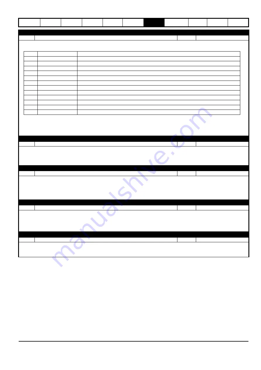
Selects the drive state that controls the relay.
The relay has 3 terminals; normally open (T41), common (T42), and normally closed (T43).
If the function selected is at 0 (Off), the common is connected to the normally closed terminal. When the function selected is at 1 (On), the common
is connected to the normally open terminal.
P6.09
T11 Digital Output 1 Function Select
Range:
0 to 11
Default:
3 (At Zero)
Selects the drive state that controls the digital output signal.
See the list of drive state options in
T41-T43 Relay Function Select
(P6.08)
T11 Digital IO 1 Type
(P6.04) must be set to Digital Output (1) or Digital Output Inverted (4) for this parameter to have an effect.
P6.10
T11 Frequency/PWM Output Function Select
Range:
0 to 17
Default:
0 (None)
Selects the output function that Digital IO 1 should represent in Frequency or PWM output types.
See the list of output function options in
T6 Analog Output Function Select
(P6.06).
The absolute value of the chosen parameter is scaled such that maximum output is equivalent to the parameter's maximum value. It can be further
scaled by
T11 Frequency/PWM Output Scaling
(P6.11). See
T11 Digital IO 1 Type
(P6.04) for setting the output type.
P6.11
T11 Frequency/PWM Output Scaling
Range:
0.000 to 40.000
Default:
1.000
Defines the scaling factor for Digital IO 1 in
Frequency
(2) and
PWM
(3) types.
An automatic scaling takes place when parameters are selected for this output such that the output will be at full scale when the parameter value
is at its maximum value. Some parameters do not reach their maximum values and so this parameter is provided for the user to apply further
scaling.
P6.12
Negative Logic (NPN Sensor) Select
Range:
0 to 1
Default:
0 (Positive Logic)
By default the digital inputs are Positive Logic inputs (sinking inputs) to suit PNP sensors. This parameter allows the digital inputs to be set to
Negative Logic inputs (sourcing inputs) to suit NPN type sensors. When analog inputs are used as digital inputs, they do not source or sink current,
but the logic is inverted when this parameter is set. This parameter has no effect on the digital output or analog inputs.
Value
Function
Description
0
Disabled
Always Off
1
Drive Running
On if the drive is running
2
At Speed
On if the output speed is within 1 Hz of the reference
3
At Zero
On if the output is within 2 Hz of 0 Hz
4
Under Voltage
On if the drive is in the under voltage state
5
External Error
On if the external error input has been set
6
Drive Ready
On if the drive is ready to run (not inhibited by a hardware enable input)
7
Drive Healthy
On if the drive is healthy (not in error) (active alarms do not make the drive unhealthy)
8
Current Limit Active
On if the drive is limiting the output current
9
Reverse Running
On if the drive is running in the reverse direction
10
An In Current Loss
On if an analog input current loss has been detected
11
Threshold Detector
On if the threshold detector is active
Содержание COMMANDER S100
Страница 118: ...0478 0650 02...


