Drive parameters Communications
Commander S100 User Guide
53
6.4 Connecting motor thermistors
To protect the motor, the drive will estimate the temperature of the motor and limit the overload period available when the temperature estimate
crosses a threshold. If the motor is to be run at a low speed with a heavy load or to protect against a motor fan failure, additional protection using an
embedded motor thermistor may be required. The thermistor used by motor manufacturers may vary. To connect a PTC or NTC thermistor follow the
steps below:
STEP 1: Wiring the thermistor.
•
Connect the thermistor at R
2
and a resistor at R
1
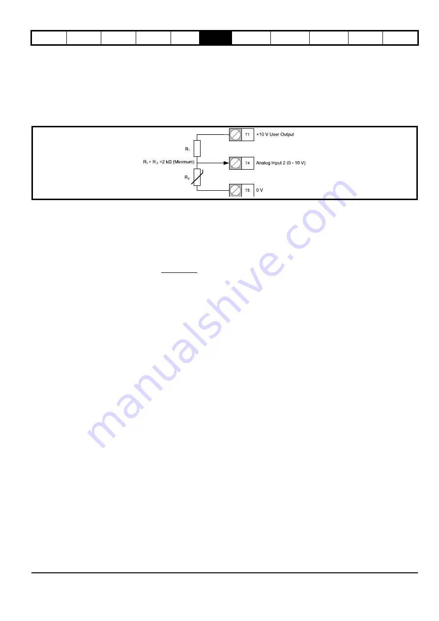
shown in Figure 6-1. The resistor at R
1
would ideally be equal to the nominal resistance of R
2
but may need to be increased so that the total resistance between T1 and T5 remains greater than 2 k
Ω
to avoid overloading the +10 V circuit.
Figure 6-1 Connecting a thermistor
STEP 2: Input setup
•
Ensure
Analog Input 2 Type
(P6.02) is set to Voltage (0).
STEP 3:
•
Set
Threshold Detector Selector
(P5.12) to Analog 2 Percentage (9).
•
Set
Threshold Detector Level
(P5.13) to the level at which the error should occur and the drive should stop running the motor. The level can be
calculated from the equation below:
Where
R
1
= The resistance of R
1
R
2
= The resistance of the thermistor when the error should occur.
•
Set
Threshold Detector Function Select
(P5.17) to External Error (14)
•
For an NTC thermistor, or a thermistor where the resistance decreases as the temperature increases, set
Threshold Detector Output Invert
(P5.16) to 1.
Threshold Detector Level
(P5.13) =
R
2
x
100
R
1
+ R
2
Содержание COMMANDER S100
Страница 118: ...0478 0650 02...


