108
Chapter 7
535-PROF User's Manual
Applications
DT
τ
RT
63% of Final PV
PV
Time
➜
Final PV
Control Output
3. Set
RESP. TIME.
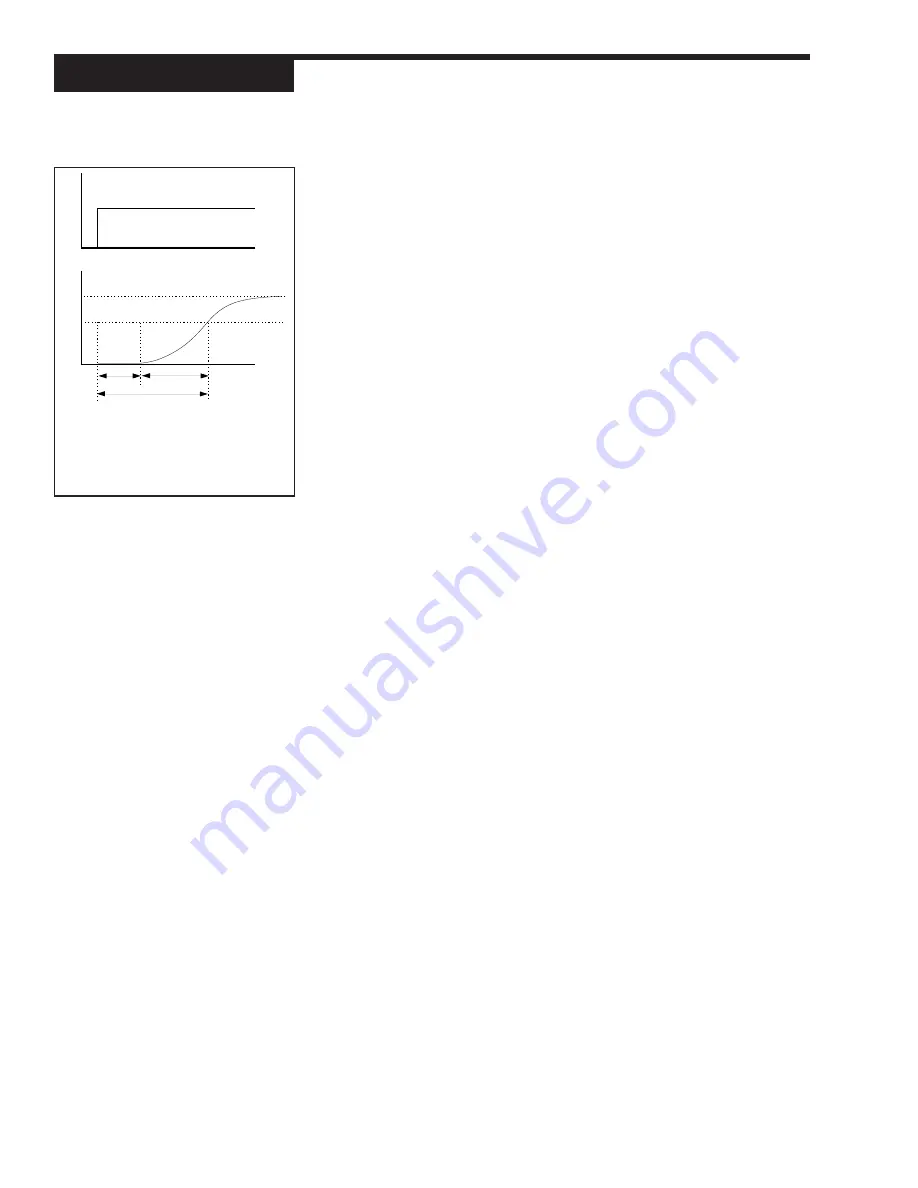
The response time is the most critical value in Adaptive Tuning. Response
time represents the time lag from a change in valve position (controller output)
to a specific amount of change in process variable. Specifically, Response
Time is equal to the Deadtime of the process plus one Time Constant. The
Deadtime is the time between initiation of an input change and the start of an
observable response in the process variable. The Time Constant is the
interval of time between the start of that observable response and the point
where the process variable reaches 63% of its final value. (See
Figure 7.16).
Example
After a stimulus (e.g., valve movement), if it takes 300 seconds for a process
to reach 63% of its new (expected) value, the response time is 300 seconds.
If the response time is set too short, the process will be unstable and cycle
around the setpoint. If the Response Time is set too long, response to an
off-setpoint condition will be sluggish. It is generally better to use too long a
response time than too short.
Self Tuning with Multiple Sets of PID
For both Pretune and Adaptive Tune, the tuned set of PID is that which is active
upon initiation of the tuning function.
The controller cannot trip to other PID sets (based on trip point or the digital in-
put contact) until Adaptive Tuning is disabled. However, if the PID set is tied to
the corresponding local setpoint, the active PID set values will change with the
local setpoint.
Each PID set has 5 parameters that control its function—proportional band, reset,
rate, manual reset (or loadline), and trip point. For each set (2 thru 8), these values
have to be manually set.
1. Press
MENU
to access the
TUNING
menu.
2. Set values for parameters 1 thru 20 (these include the first PID set).
3. Press
MENU
to access these parameters for each additional PID set
(2 through 8):
PROP. BND, RESET, RATE, MAN. RST.
and
TRIP
.
Self Tune with Time Proportioning Outputs
When using either the Pretune or the Adaptive Tune with a time proportioning
output, use as short of a cycle time as possible within the constraint of maintaining
a reasonable life on relays, contacts or heating elements.
Self Tune with Control Valves
In many systems utilizing a control valve, the point at which the control valve
begins to stroke does not coincide with 0% output, and the point at which it
completes its stroke doesn’t coincide with 100%. The parameters
LOW OUT
and
HIGH OUT
in the
CONTROL
menu specify the limits on the output. Set
these limits to correspond with the starting and stopping point of the valve’s
stroke. This prevents a form of “windup” and thus provides the adaptive control
algorithm with the most accurate information.
For example, in manual the control output was slowly increased and it was noted
that the control valve started to stroke at 18% and at 91% it completed its stroke.
In this case
LOW OUT
should be set at 18% and
HIGH OUT
at 91%.
DT =
Dead Time
τ =
Time Constant
RT =
Response TIme
Figure 7.16
Deadtime and Time Constant


