background image

Operation with the Touch Panel 


LMV1000 (G)(E) AIR-COOLED LASER MARKER 

6-30 

990-541 

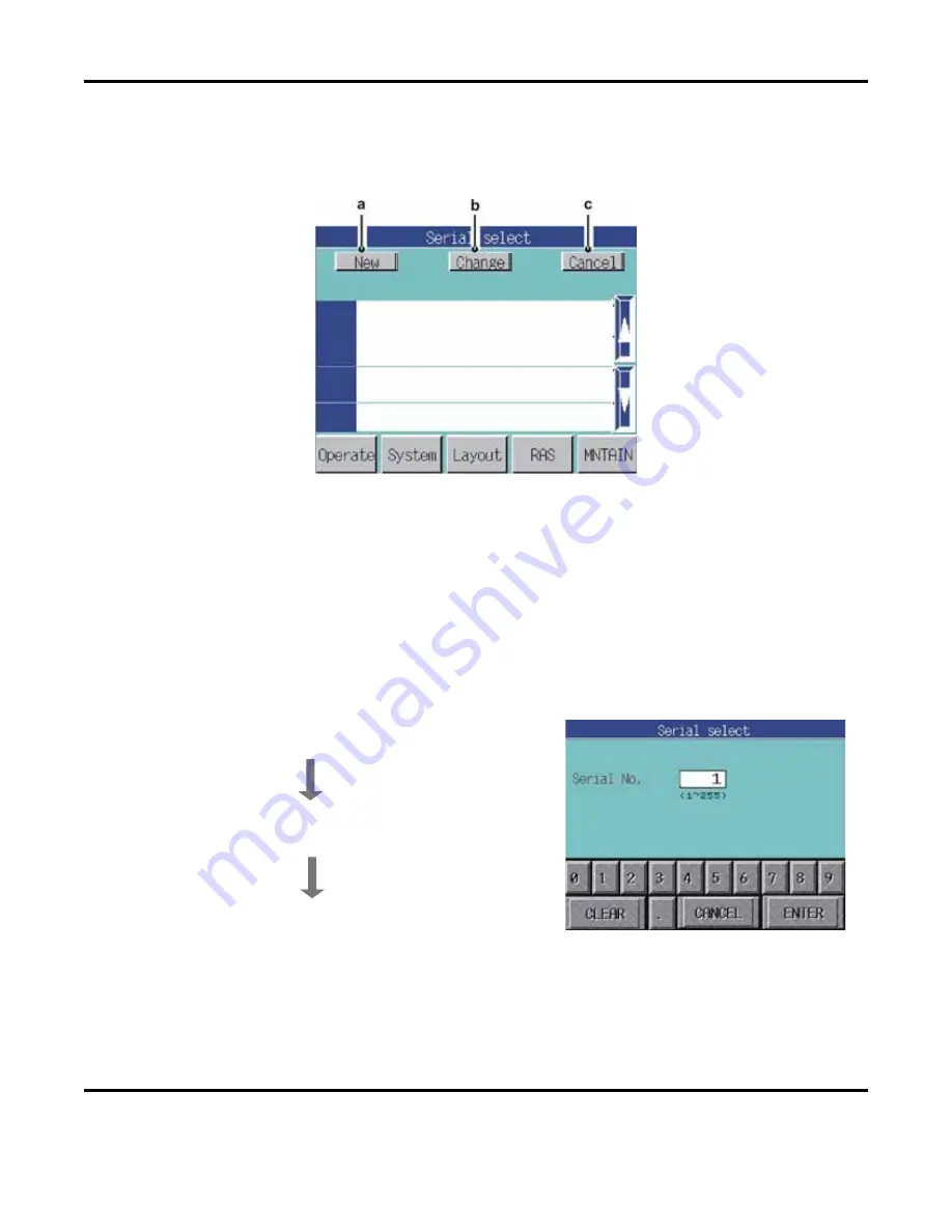
4.  Serial Select Screen 

Used to define serial number data.  You can register 255 serial numbers (1 to 255).  Press the  

Serial


button on the 

Select font

 screen to gain access to the Serial select screen. 


a. New 


Defines a new serial number. 

b. Change 


Changes the contents of a previously registered serial number. 

c. Cancel 


Cancels the set contents. 


Defining a new serial number 

1.


Press the  

New

  button.  The screen will change as 

shown on the right. 


2.


Enter the serial number you want to register.  The 
setting range is 1 to 255. 


Содержание LMV1000

Страница 1: ...USER S MANUAL 990 541 Revision C November 2013 OPERATOR MANUAL FOR THE LMV1000 G LMV1000 G E ML 7110A ML 7110A CE ML 9000A ML 9000A CE LD PUMPED YVO4 AIR COOLED LASER MARKER Using Fine Marker Software...

Страница 2: ...thout the written authorization of MIYACHI AMERICA CORPORATION Printed in the United States of America Revision Record Revision EO Date Basis of Revision A 19841 3 04 Production Release B 20722 3 06 I...

Страница 3: ...ter 4 Installation and Connection Installation Location 4 1 Power Supply Connection 4 2 Controls and Head Unit Connections 4 3 Control Unit and Operation Unit Connections 4 4 Installation of the Marke...

Страница 4: ...Condition Setup Screen 7 111 Calendar Marking Setup Screen 7 117 Chapter 8 Communication Function Option Connecting Cable Specifications D Sub 9 pins 8 1 Communication Procedure 8 2 Communication Prot...

Страница 5: ...Filters 12 2 Clean and Replace Protective Glass 12 3 Replace the LD Pumping Laser Diode 12 4 Resetting Changing the LD Module system parameters 12 9 Memory Card Back up 12 10 Restoring Memory Card Co...

Страница 6: ...ng company immediately to file a claim and notify Miyachi America at Miyachi America 1820 South Myrtle Avenue P O Box 5039 Monrovia California 91016 Phone 626 256 4128 FAX 626 303 5396 E mail info miy...

Страница 7: ...002 1010 and 1040 for Class IV laser devices Reference CDRH Accession number is available upon request For details refer to the following standards LMV1000 ML 7110A CDRH Certified to be in compliance...

Страница 8: ...LMV1000 G E AIR COOLED LASER MARKER viii 990 541...

Страница 9: ...LMV1000 G E AIR COOLED LASER MARKER 990 541 ix...

Страница 10: ...meaning of the words and symbols is as follows DANGER DO NOT TOUCH THE INSIDE OF THE LASER MARKER UNNECESSARILY High voltages are present inside the equipment cabinet Do not touch the inside of the La...

Страница 11: ...able The power cable and connecting cables may be damaged which can cause electric shock short circuit or fire If any part needs to be repaired or replaced consult Miyachi America or your distributor...

Страница 12: ...ay from the laser use the operation unit to control the laser functions Install the operation unit in front of the work area at the height of the Operator s elbow and within easy reach 2 3 feet as sho...

Страница 13: ...ver apply the laser to flammable or combustible materials NEVER cover the Laser Marker with a blanket cloth etc during operation Heat generated by the operating Laser may ignite a blanket or cover Do...

Страница 14: ...emperature fluctuations Do not use the laser marker in the following places Where there is considerable dirt dust or oil mist where the laser marker may be subjected to vibration or impact where the l...

Страница 15: ...data on memory card may be destroyed If the data on memory card is destroyed marking will not be possible and the laser marker may not power up correctly x For stable marking allow the Laser Marker to...

Страница 16: ...e the service life of the pumping LD Do not turn off the Laser Marker with the Emergency stop button x The pumping LD has a finite life As time passes the output power will gradually degrade When the...

Страница 17: ......

Страница 18: ...ictures Fine marking is easily possible It is optimal for marking on minute parts x Non contact marking Marking onto a curved or concave plane is possible LMV1000 G E ML 7110A CE ML 9000A CE Laser Mar...

Страница 19: ...n the workpiece for accurate marking x Eight types of marking ranges available LMV1000 E ML 7110A CE You can select the following marking ranges 39 mm 80 mm 120 mm 100 mm by 100 mm 150 mm by 150 mm 21...

Страница 20: ...0 541 3 1 CHAPTER 3 NAME AND FUNCTION OF EACH SECTION 1 Controls Front 1 Control Unit Accommodates the control board the RF unit and the power supply unit The operational status of the Laser Marker is...

Страница 21: ...s equipment Do not touch them d Emergency Stop Button Press this button when you want to stop the equipment during operation When pressed the marking operation stops and LD is turned OFF Once pressed...

Страница 22: ...Marker system 6 Panel Indicators Indicators light up on the equipment under the following conditions POWER The power is supplied to the equipment READY The LD is turned on SHUTTER The main safety shut...

Страница 23: ...gainst overcurrent and leakage current Normally this is kept ON 2 Power Supply Terminals Connect to the power cable These terminals connect to the A C power source 3 Cooling Connector Supplies power t...

Страница 24: ...Pin Male Used for controlling the Marker from an external device Insert the factory supplied loop back connector when external control is not used 10 Extended I O Controlling Connector D Sub 15 Pin F...

Страница 25: ...of the Control Unit Improperly setting these switches will prevent the Marker from operating correctly CAUTION When a PC and the Operation Unit are connected to the Marker do not operate them simultan...

Страница 26: ...re of the head unit may rise which can cause the Marker to malfunction Remove the air filter and clean it with a neutral detergent every 1 6 months depending on the operating environment See Chapter 1...

Страница 27: ...interlocks should be defeated is when you perform maintenance on the Head Unit 6 Fan Used to draw the heat from the head unit to the exterior 7 Y axis Galvanoscanner This driver contains the Y axis d...

Страница 28: ...me stand to prevent marking distortion due to vibration x Do not operate the unit where there is considerable dirt dust oil mist chemicals fumes moisture or near a high frequency noise source x The am...

Страница 29: ...the power supply cable 6 5 feet 2m maximum length to the power supply terminals NOTE Connect the ground wire to the FG terminal using Class D grounding Black AC Line L White AC Neutral N Green AC Grou...

Страница 30: ...he Grounding Cable v Connect a grounding wire between the grounding screw on the Head Unit v and the FG screw on the Power Supply Terminal v Secure all cables 3 Connecting the Optical Fiber vi Remove...

Страница 31: ...to the Control Unit 5 Installation of the Marker Program 1 When the CD is inserted into the CD ROM drive on the remote PC the screen on the left will appear Select the Standard system Communication pa...

Страница 32: ...Company then select Next 5 After the registration information is confirmed click on Next 6 Confirm the installation destination then select Next If you would like to change the installation directory...

Страница 33: ...8 Click on Next to start the software installation 9 During installation the computer may have to be restarted If prompted restart the system and then continue the installation from step 1 above 10 W...

Страница 34: ...display on the Touch Panel Display after the system completes a series of self diagnostic tests All of the Panel Indicators will light up during the self diagnostic tests CAUTION Do not turn off the...

Страница 35: ......

Страница 36: ...eration screen will display NOTE If an error is displayed on the screen record the error and contact us at the address shown in the front of this manual CAUTION Do not turn off the Main Switch during...

Страница 37: ...the LD Laser Diode will turn ON When the LD is turned on the Start button will change to Starting ready When the Laser is ready the Laser button will change to green The Laser Marker is now ready for...

Страница 38: ...working distance depends on the f theta lens installed and the wavelength of the Marker Refer to the table below for setting the approximate working distance Use this value as a starting point and adj...

Страница 39: ...ving Layout File for information on saving a design layout Press the layout file name you want to load on the Layout Select screen When five or more layout files are registered they all cannot be disp...

Страница 40: ...k button will change to MKG when the laser is ready to mark c Press the MKG button to start marking During a mark sequence the MKG button will change to Now MKG 5 Guide Beam Marking LMV1000 E ML 7110A...

Страница 41: ...he marking process will begin Instead of projecting an IR beam a visible guide beam will project The MKG button will change to Now MKG 6 Stopping a Mark Process When the Stop button is pressed during...

Страница 42: ...yout Layout file A file that contains the layout Layout number The number of the layout file Line A group of characters or graphics spaced apart vertically see below In the figure above the layout con...

Страница 43: ...sage will display When finished entering all characters press the ENT button followed by OK In the figure at right the layout file named SAMPLE is registered 5 When the Layout Straight line screen app...

Страница 44: ...isplay the line number then press the line number to select Use the Delete screen to delete the characters 9 Once the layout file has been created the line position will be displayed as a text frame i...

Страница 45: ...ge Cooling LD is displayed do not turn off the Main Power Switch If the Main Power Switch is turned off when the LD is cooling down the service life of LD will be reduced Also the system data on the m...

Страница 46: ...when a PC is connected to the Control unit the Control unit is recognized as a USB drive by the PC Turn off the PC before turning off the Control Unit x Do not turn off the Main Power Switch for at le...

Страница 47: ......

Страница 48: ...Avoids over lapping intersections Positions the absolute origin Sets the jump speed and the control method of the safety shutter Displays and changes the straight line character data Displays and cha...

Страница 49: ...the ENTER button to cancel an input value 2 Character Entry Choose a setting item Touch a field to enter or change characters When you do the Input Character string shown on the right will display Ac...

Страница 50: ...button is pressed Guide and Guide ON are alternately switched c Unlock MKG Now MKG Releases the software lock and allows the Marker to begin marking The Marker can not be operated when locked Each ti...

Страница 51: ...aser Diode is turned off h Screen Switching Buttons The five buttons located in the lower portion of the screen indicate the names of the other function screens i Operate Displays the Operate screen i...

Страница 52: ...a line c Frequency Sets the projecting interval of the laser beam This value can be used to adjust the output peak power to get the desired marking result d Bold line Switches to the Bold line functio...

Страница 53: ...Wobble Creates a line by marking a spiral pattern b Contour correction When the thick line function is used the shape of the mark can be adjusted where lines intersect sharply ON Truncates the corners...

Страница 54: ...b as shown on the left Using this method the mirror changes direction at the start point and the end point In edge control the mirror is positioned beyond the start and end points and move from posit...

Страница 55: ...on Removal Screen When a character or figure has intersecting lines t X Q etc the marked intersection points will appear dense This can be avoided by the intersection removal function a Auto Removal M...

Страница 56: ...Pulse Suppression value 5 Offset Screen Positions the absolute origin for all layouts below The absolute origin is set to coordinates 0 0 a Origin return control ON Every time the marking ends the sca...

Страница 57: ...int of one object mark to the start point of the next object a Safety shutter control INTRLOCK The safety shutter is controlled by the marking start signal Firm OP The safety shutter is always open wh...

Страница 58: ...There are 2 types of layout screens the Lay Out Straight line screen and the Layout Arc screen 1 Layout Straight Line Screen a Last Next Selects the next line in order when two or more lines data are...

Страница 59: ...e Y coordinate of the start point relative to the absolute origin i Tilt Sets the character angle in the figure at right The lower left of the line becomes the reference point with the horizontal line...

Страница 60: ...tring is center justified RIGT The character string is right justified Extn Redu Adjusts the character string to fit within the character string length d ARNGE LG Sets the character line length e ARRA...

Страница 61: ...0 then the character origin is the same as the absolute origin b ORIG Yaxis Sets the origin of the Y coordinate axis When the Y coordinate value is 0 the character origin is the same as the absolute o...

Страница 62: ...cy value has a higher priority h MKG Speed Sets the marking speed i Blok No Divides a line into several groups called a block Normally all characters in a line are marked with the same font Additional...

Страница 63: ...20 0A is defined on the System set screen the marking process would occur as follows Line No Setting Current Actually Used 1 20 0A 2 25 0 25 0A 3 30 0 30 0A 4 30 0A 5 25 0 25 0A 4 Layout Arc Screen N...

Страница 64: ...the circumference of the defined circle e ST angle Indicates the start position of the characters on the circumference of the defined circle in degrees f Radius Indicates the radius of the defined ci...

Страница 65: ...tified CTRG The character string is center justified RIGT The character string is right justified Extn Redu Adjusts the character string to fit within the character string length e ARNGE LG Sets the a...

Страница 66: ...er String Screens There are six screens in total When the w or y button is pressed the screens are switched as shown by arrows below When Kanj button is pressed on the Hiragana input screen the Kanji...

Страница 67: ...egistered in the block number displayed in this field c Font select column Selects the font or graphic to use When this column is pressed the Select font screen shown on the right is displayed Select...

Страница 68: ...vailability and Serviceability screen displays the status of the Marker For error code definitions see Chapter 13 Troubleshooting a Last INFO Updates the screen b n p Used to scroll through the list o...

Страница 69: ...d Reset Resets the LD Integral to 0 Press and hold the button for several seconds see Reset Screen e Password Switches to the Password screen see Password Screen f Option Switches to the Option screen...

Страница 70: ...D set up screen a OK Clears the LD Integral time and returns to the Maintenance screen b CANCL Returns to the Maintenance screen c LD wave length Used to define the wavelength of a replaced LD module...

Страница 71: ...tely four seconds until the password Registration screen appears 1 Set the password on the Registration screen 2 If the Password button is pressed when the password has been set a valid message will a...

Страница 72: ...enable external control Local Layout No and marking start are set through the touch panel PC and RS 232C Remote Layout No and marking start are set through the external I O b EXTN IO Switches to the E...

Страница 73: ...e Sets the delay time for the strobe signal b ACK wait time Sets the acceptable communications wait time used for error monitoring Barcode screen The contents of the registered layout file are automat...

Страница 74: ...cter file registered here is converted to a QR code format The setting screen is displayed before switching to the Bar code screen e Data Switches to the Data code screen The character file registered...

Страница 75: ...d graphic data b Delete Used to delete selected graphic data Press the Delete key then select the graphic data to delete When the screen shown on right is displayed press Enter to delete the data or p...

Страница 76: ...ove a capacity to resist distortion of large codes Based on the Model 1 code Micro QR The efficiency of printing area is increased with the use of only one position pattern to fit to very small codes...

Страница 77: ...rial button on the Select font screen to gain access to the Serial select screen a New Defines a new serial number b Change Changes the contents of a previously registered serial number c Cancel Cance...

Страница 78: ...the present value displayed on the screen Zero Suppress When ON is selected 0 s are added to the left of the serial number to fill the Digit count Displays as 00001 00002 00003 etc Min When selecting...

Страница 79: ...l number registration 1 Press the Change button When the screen changes select the serial number you want to change 2 Press the ENTER button 3 When the Serial set screen appears change the necessary i...

Страница 80: ...acters each time you mark NOTE You can register 255 variable data strings 1 to 255 a New Creates a new variable data string b Change Changes the contents of a previously created variable data string c...

Страница 81: ...ata string registration 1 Press the Change button 2 When the screen changes select the variable data number you want to change 3 Press the ENTER button 4 When the Input character string screen appears...

Страница 82: ...mber of the equipment and the Software version of the operation unit In the figure above the model number is ML 7110A The software version of the operation unit is Ver00 01C 2003 01 16 b CPU1 Displays...

Страница 83: ...even if the current is raised 2 to 3A within 1000 hours the protective glass may be dirty See Chapter 12 Maintenance for cleaning instructions If the problem is not resolved contact Miyachi America b...

Страница 84: ...can both be connected to the Control Unit but only one can control the Marker at a time x To use the Operation unit and a computer connected with the USB cable display the Operate screen of the Operat...

Страница 85: ...G E AIR COOLED LASER MARKER 7 2 990 541 3 Computer Screen settings 1 Double click the Display icon in the control panel The Display Properties window will open 2 Select the Screen Saver tab 3 Set the...

Страница 86: ...r 1 Operation panel Displays the laser startup marking and other basic operational functions 2 Tool bar Used to access the different setup screens System Sets the laser parameters and edge control fun...

Страница 87: ...current frequency and other parameters common to the system Layout Creates or edits a marking layout Graphic Creates or edits graphic patterns used for marking or reads a BMP file Dyn Sets variable da...

Страница 88: ...Start Stop Local Start Stop Laser Marking Start End Stop Guide Marking Single shot Start End Continuous Start End Stop Select layout List Select Set Current Transfer Suspend Range 5 48A Pitch 0 1A Def...

Страница 89: ...ent offset 0 200 1 100 Marking speed 1 7000mm s 1mm s 300mm s Cycle frequency CW 0 0 99 9kHz 0 1kHz 5kHz Thick line function None None Standard High quality Fluctuation Contour correction None Line wi...

Страница 90: ...ump 0 1000ms 0 1ms 1ms Shutter open close time Shutter open delay time 50 50ms 0 1ms 0 3ms Shutter close delay time 50 50ms 0 1ms 0 3ms T shutter control ON Origin return control ON Lens Offset Offset...

Страница 91: ...on 0 05 280mm 0 001mm Identical pitch 0 05 280mm 0 001mm 0 05 280mm 0 001mm Character interval specify Reverse marking Overwrite 1 32767 times 1 time Comment 0 30 characters 1 character Linear vertica...

Страница 92: ...0 360 0 1 Expansion 0 360 0 1 Identical Pitch 0 360 0 1 Character interval specify 0 360 0 1 Reverse marking Overwrite Comment 1 character 0 30 characters Transfer control X axis 32000 32000 1 0 Y ax...

Страница 93: ...end created line Repetition number of times 1 32767 1 0 Comment 1 character 0 30 characters 0 10s 0 001s 0 000 Shutter control Shutter open time Range Pitch Default Line Number Compression Compressio...

Страница 94: ...ta code Serial Bar code 39 Serial Bar code ITF Character string Display function Magnification Origin display Re display Transfer control separate display Transfer control next display Batch display C...

Страница 95: ...dependent file also Copy End End CAUTION Set the Number of lines and Number of sequences so that their multiplied value is 500 or less 5 Graphic Graphic Expand Reduce Move center Draw line Draw curve...

Страница 96: ...er Delete Copy Copy source Copy candidate Copy destination Option Prompt overlay at copy Copy End Import Read file created by FAL Read binary file Remove intersection at import Batch import Ruler disp...

Страница 97: ...racter Graphic Flower letter Bar code 39 Invert bar code 39 Bar code ITF Invert bar code ITF Marking character string Save Comment set Update display Transfer End 7 Serial Range Pitch Serial Comment C...

Страница 98: ...990 541 7 15 8 Set Set Folder set Drive name Work folder New Set Maintenance Layout list Layout Store list All selection All cancel Update display Transfer End Graphic list Graphic Store list All sel...

Страница 99: ...setting Re read End 10 Condition Range Pitch Default Condition Marking Speed 1 7000mm s 1mm s LD current 5 48A 0 1A Frequency CW 0 99 9kHz 0 1kHz Thick line function None None Standard None High quali...

Страница 100: ...r character space Both ends marking Both ends space Bar code ITF Start Stop marking section Start Stop space section Thick marking section Thin marking section Thick space section Thin space section R...

Страница 101: ...n panel window b External control Local Layout Number and marking start can be set through the touch panel computer and RS 232C Remote Layout Number and marking start can be set through the external I...

Страница 102: ...guide beam Used to select laser or guide beam output LMV1000 E ML 7110A CE only iii Marking instruction Press Marking to display the marking instructions dialog box shown below Select single engined o...

Страница 103: ...ttempt an on line connection k Consumables replacement indicator Clicking this indicator will display the list of consumables Red Consumables need replacement Maintenance is necessary Green Consumable...

Страница 104: ...or the operator The Marker will still function properly but replacement should be scheduled at the earliest convenient time a LD module Total time Indicates the total running time of the LD module Thi...

Страница 105: ...in black Each time an error occurs the date time location error code error description and remedy are displayed and are written in the historical file File menus Copy Save Used to save a copy of the...

Страница 106: ...7 OPERATION WITH A PC LMV1000 G E AIR COOLED LASER MARKER 990 541 7 23 5 System Parameters Screen 1 Common Items Displays the current control unit set values...

Страница 107: ...ile menus Function Description Read Reads operating parameters from a file and displays them on the screen Save Saves operating parameters into file End Closes the System parameters screen View menu O...

Страница 108: ...laser beam overlap is avoided Line width Thick line width is designated Line count Number of laser beams used to produce a thick line Amplitude width Sets the thick line fluctuation width Amplitude fr...

Страница 109: ...arting point End point adjusting distance Sets the scanner distance after the end point Effective crossed axes angle Sets the maximum crossed axes angle Accelerator coefficient 1 Sets the scanner opti...

Страница 110: ...start point of the next line Jump Wait time after jump Sets the wait time after the end point has been marked Shutter open delay time Sets the shutter open delay time Shutter open close time Shutter...

Страница 111: ...7 OPERATION WITH A PC LMV1000 G E AIR COOLED LASER MARKER 7 28 990 541 Lens Offset Item Description X axis X axis layout offset Y axis Y axis layout offset Theta axis Angle layout tilt offset...

Страница 112: ...LASER MARKER 990 541 7 29 Transfer unit control Item Description Strobe output delay time Sets the output strobe signal delay time ACK wait time Sets the error monitor wait time CAUTION Setting the AC...

Страница 113: ...WITH A PC LMV1000 G E AIR COOLED LASER MARKER 7 30 990 541 Parameter Change wait time Item Description LD current Sets the LD current response wait time Cycle frequency Sets the cycle frequency respon...

Страница 114: ...ems When linked to the Layout creation screen the dialog box appears as shown on the right Select a desired button New Displays a dialog box for new mark field Edit Displays the Layout file selection...

Страница 115: ...e Saves data under the same file name Save As Saves data under another file name Delete Displays the Layout file deletion screen when layout file is closed Copy Displays the Layout copy screen Print P...

Страница 116: ...ED LASER MARKER 990 541 7 33 2 Basic Procedure of Layout Creation New Input the name of a file to create Layout file selection From the file list work folder contents select a file to edit CAUTION Use...

Страница 117: ...UTION Files layout graphic parameters created by the user are controlled by working folders on the setup screen NOTE The number of files created in a work folder depends on the limit of OS operating S...

Страница 118: ...ndidate Displays the list of files to be copied Double clicking a filename will cancel the transfer Option At the time of the Copy replacement verification Displays a prompt if the copy destination ha...

Страница 119: ...n Re display After the layout is modified a re display will refresh the contents of the display Line Number and Shape Function must be defined Line Number Each line is assigned a number Select the num...

Страница 120: ...tions optional Select the List reference button to display the list of condition files See Example of Layout Creation Setting the marking conditions for details CAUTION When short marking cycle times...

Страница 121: ...anjis are used for marking 2nd standard Characters registered as second standard characters JIS font alphanumerics are used for marking Variable Variable data number is designated 1 to 255 Serial Numb...

Страница 122: ...7 OPERATION WITH A PC LMV1000 G E AIR COOLED LASER MARKER 990 541 7 39 When a BMP file is selected as a graphic the Color palette setup window will appear Details of shape function a Linear horizontal...

Страница 123: ...ft justify Marking is left justified by the defined distance 0 05 to 280 0 001 Center justify Marking is center justified by the defined distance 0 05 to 280 0 001 Right justify Marking is right justi...

Страница 124: ...of the marked character is defined in this field 0 05 to 280 0 001 Tilt The tilt angle of the marked character is defined in this field 0 to 360 0 1 Character space The character space is defined in t...

Страница 125: ...OL Left justify Marking is left justified by the defined distance 0 to 360 0 1 Center justify Marking is centered justified by the defined distance 0 to 360 0 1 Right justify Marking is right justifi...

Страница 126: ...acter is positioned away from the arc center d Carriage control used with Motion Control Card Item Meaning Range Pitch 2 shaft 4 shaft The number of motion directions is defined 2 and 4 X shaft X dire...

Страница 127: ...ng Range Pitch Offset X X axis offset value 280 to 280 0 001 Offset Y Y axis offset value 280 to 280 0 001 Comment Arbitrary description comment is not marked 30 characters max CAUTION Any lines marke...

Страница 128: ...fined 0 001 to 280 0 001 Start position X Position to start marking on the X axis 280 to 280 0 001 Start position Y Position to start marking on the Y axis 280 to 280 0 001 Comment Arbitrary descripti...

Страница 129: ...t line Defines which object line to perform the subroutine on 1 to n 1 Repetition number of times The defined number of times to process the subroutine 1 to 32767 1 Comment Arbitrary description comme...

Страница 130: ...A PC LMV1000 G E AIR COOLED LASER MARKER 990 541 7 47 h Shutter control Item Meaning Range Pitch Shutter open time Defined shutter open time 0 to 10 0 001 CAUTION Characters can not be selected in shu...

Страница 131: ...mount of character and graphic compression compressed length 1 to 100 1 Comment Arbitrary description comment is not marked 30 characters max CAUTION The character height will not change by compressio...

Страница 132: ...OLED LASER MARKER 990 541 7 49 j Loop Item Meaning Range Pitch Times End by circle Number of times to repeat 0 to 32000 1 Comment Arbitrary description comment is not marked 30 characters max CAUTION...

Страница 133: ...Example of Layout Creation a How to create a Layout i From the tool bar select the Layout button ii Press the New button to create the new layout iii Input an arbitrary layout file name and then press...

Страница 134: ...G E AIR COOLED LASER MARKER 990 541 7 51 b Editing the layout i Select the Edit button ii From the file list select an existing layout file to edit then press the Select button The selected layout fi...

Страница 135: ...Shape Function to Linear horizontal This displays the same contents in the Shape Function column of the Character input iii Define the character positions by setting the Start position X and Start po...

Страница 136: ...owing section describes how to add first standard characters on a 2nd line in a linear horizontal direction i Select the Add button When prompted to add a 2nd line choose Yes ii Set the Shape Function...

Страница 137: ...out graphic display CAUTION If the Character arrangement was set to other than Left justify the expansion identical pitch and character interval must be specified e How to insert line The following se...

Страница 138: ...aracter arrangement as Center justify Input the position in mm vii Select 1st standard as the character type then enter the following character string 012345ABCDE viii Select Re display and verify the...

Страница 139: ...Character space and Character width vi Set the Character arrangement to Left justify The first character in upper justify or the last character in lower justify is positioned at the defined X and Y p...

Страница 140: ...rt angle and character height v Define the Character direction IL or OL vi Define the Character arrangement to Left justify vii Define the Character type as 1st standard At the Character string key in...

Страница 141: ...n Y iii Define the character height and tilt iv Set the character arrangement to Left justify v Define the character type as Graphic Highlight the desired graphic then choose the Select button The Lay...

Страница 142: ...ine number is 2 ii Change the character type from No designation to Graphic The Graphic select screen will appear Select a graphic to add iii Select the Re display button and verify the added graphic...

Страница 143: ...be to use the offset function to reposition these character strings i Select the 5th line then press the Insert button to insert a line between the 4th and 5th character strings Choose this entry as...

Страница 144: ...Offset X and Offset Y values iv Set the Relevant line to 1 line or several continuous lines located above the subroutine line v Input the numbers of repeat times in the Repetition number field NOTE Be...

Страница 145: ...ard characters 12345 as described below ii Define the Shape Function as Linear horizontal iii Set the character Start position X and Start position Y to 0 iv Define the character height and tilt chara...

Страница 146: ...he matrix function on the 1st line All character strings listed after the matrix shape function line will share the common matrix properties n Setting the marking conditions This section describes how...

Страница 147: ...unt in the appropriate spaces and save the data entries v Select the End button to return back to the Layout creation screen Setting the layout marking conditions The marking conditions created in the...

Страница 148: ...ted without saving you will be prompted to save the changes Select Yes to save the contents viii The selected contents will appear on the marking conditions column Reconfirm these conditions then sele...

Страница 149: ...ext marking conditions are selected In the above example where marking conditions were selected on the 1st and 2nd lines marking will be made under Conditions 1 for the 1st and 2nd lines and under Con...

Страница 150: ...the layout screen and select overlay to save them i Select End from the File menu or click on the End button on the upper right of the screen ii A message will appear prompting the end of the session...

Страница 151: ...LMV1000 G E AIR COOLED LASER MARKER 7 68 990 541 7 Graphic Creation Screen This Marker software can only import BMP graphic files 1 Common Items To display the last graphical Data entered select Grap...

Страница 152: ...Used to inputs graphic data b File menus Function Description New Creates a new graphic file Open Opens a previously created graphic file Save Saves the graphic file under the same filename Save As S...

Страница 153: ...r Registers saves a new file b Open a graphic i Thumbnail characters of created graphic files will appear on the Graphic select list screen ii Using a mouse select a thumbnail character The filename w...

Страница 154: ...ed to define the graphic file to copy Select the file s ii Select the button to display the list of graphic files to copy Double clicking a file in the Copy Candidate field will cancel the copy proces...

Страница 155: ...ounterclockwise SP X Marking speed 1 d X d 7000mm s CU X LD current 5 to 48A PU X Cycle frequency 0 d X d 99 9kHz CW S0 X Shutter open delay time 50 0 to 50 0ms SC X Shutter close delay time 50 0 to 5...

Страница 156: ...e start point intersection is removed E intersection removal end point command Same as b except that the end point intersection is removed R arc command Draws an arc from the current points to designa...

Страница 157: ...0 G E AIR COOLED LASER MARKER 7 74 990 541 c Graphic Creation Example i How to create a graphic image ii How to close the graphic edit screen Select End from the File menu or click on the End button o...

Страница 158: ...lect New from the File menu Define a file name height and width and then press the Register button Create a square by defining Graphic creation on the screen details described previously in this chapt...

Страница 159: ...from the File menu Define a filename height and width and then press the Register button Create a circle by defining Graphic creation on the screen details described previously in this chapter Select...

Страница 160: ...from the File menu Define a filename height and width and then press the Register button Create a graphic with lines and arcs by defining Graphic creation on the screen details described previously in...

Страница 161: ...the Reading of the DXF file option Select the drive and folder containing the DXF file The list of DXF files will be displayed on the right side of the screen For this example choose MIYACHI DXF To re...

Страница 162: ...position CAD width or height A conversion will be made to the resolution of the CAD width or height so that it fits within the specified coordinate area If the maximum specified coordinate position C...

Страница 163: ...o demonstrate a typical creation of a BMP file Determine the size of the BMP marking data Marking data height 30mm Beam spot 40 m When using f 100mm lens x6 beam expander The formula for calculating s...

Страница 164: ...a file Specify the destination folder Select Copy followed by OK NOTES x The default copy destination folder is C USER x A copy cannot be performed within the same folder The source folder must differ...

Страница 165: ...select the converted BMP from the Graphic select list Specify a filename on the Color palette setup window and select the BMP file Select SH1 for a black palette and SH0 for a white palette When rever...

Страница 166: ...detection pattern is a square made up of seven modules per side 34 EQFG QFGN 34 EQFG QFGN 3WKGV QPG 2QUKVKQP FGVGEVKQP RCVVGTP KETQ 34 EQFG OQFWNG YKFG SWKGV QPG KU TGSWKTGF CTQWPF C U ODQN OQFWNG YKF...

Страница 167: ...ficiency is increased with the use of one position pattern used to accommodate very small code iii Data input mode Automatic setting Manual setting Numeric Alphanumeric Binary Kanji iv Error correctio...

Страница 168: ...7 OPERATION WITH A PC LMV1000 G E AIR COOLED LASER MARKER 990 541 7 85 b Version and the number of modules per side Model 1 Model 2 Error correction rate L 7 level M 15 level Q 25 level H 30 level...

Страница 169: ...tion pattern Module and Quiet zone are created with commands in the graphic creation program c Command Descriptions J jump command J X Y Jumps without drawing a line from the current position to a des...

Страница 170: ...rcle will be drawn If there is a distance difference in center positions between the current position and designated position the start point will not be continuous because the arc radius is calculate...

Страница 171: ...for dot marking Example Height Width 100 As shown below the registered graphic will produce a laser output for 0 001 seconds 1ms at the origin Example 3 Position detection pattern Example Height Width...

Страница 172: ...ON WITH A PC LMV1000 G E AIR COOLED LASER MARKER 990 541 7 89 Example 4 Reverse position detection pattern Example Height Width 350 As shown below the registered graphic is symmetric with respect to t...

Страница 173: ...LASER MARKER 7 90 990 541 Example 5 Quiet zone Example Height Width 20000 As shown below the registered 20000 x 20000 graphic has an origin located in the lower left of the graphic NOTE The height an...

Страница 174: ...during the encoding process Data Storage Data module will change based on the encoding conditions ECC and data type and number NOTE ECC stands for Error Checking and Correcting and is referred to as t...

Страница 175: ...ata Matrix creation program Applicable to ECC200 ii Data Matrix size Allowable Data Matrix size number of modules in row and column and the number of data bytes are as follows CVC CVTKZ UK G 0WODGT QH...

Страница 176: ...SER MARKER 990 541 7 93 c Style Indicates the Data Matrix state Number of modules 10 x 10 to 144 x 144 NOTE Not applicable to a rectangle module Maximum number of characters 100 White black reverse fu...

Страница 177: ...position is preset at point 0 0 If multiple graphic data files are marked then the mark will begin from the last coordinate position marked L line command L X Y Draws a line from the current position...

Страница 178: ...e 1 Module Example Height Width 100 As shown below the registered graphic is symmetric with respect to the origin Example 2 Module for dot marking Example Height Width 100 As shown below the registere...

Страница 179: ...SER MARKER 7 96 990 541 Example 3 L shape Example Height Width 360 Reference Use the following formula to approximate the width of the L shaped graphic 9KFVJ QH UJCRG GKIJV QH ITCRJKE EVWCN PWODGT QH...

Страница 180: ...ta Matrix over 18 modules the L shape will appear as follows Same as Example 3 Example 4 Quiet zone Example Height Width 20000 As shown below the registered 20000 x 20000 graphic has an origin located...

Страница 181: ...LASER MARKER 7 98 990 541 8 Variable Data Setup Screen 1 File menus Function Description Read Reads the variable data from the file and displays it on the screen Save Saves the variable data into a fi...

Страница 182: ...rd characters JIS font alphanumeric are used for marking Flower character Fancy alphanumeric letters are used for marking Graphic Graphic file is selected from thumbnail characters Cannot define input...

Страница 183: ...R MARKER 7 100 990 541 9 Serial Number Data Setup Screen 1 File menus Function Description Read Reads the serial No data from the file and displays it on the screen Save Saves the serial No data into...

Страница 184: ...rrent or initial value 0 232 Digit count Sets the maximum number of digits to mark 1 10 Increase Decrease Increase or decrease interval mark value 32 32 Zero suppress Suppresses leading 0 s if the num...

Страница 185: ...7 OPERATION WITH A PC LMV1000 G E AIR COOLED LASER MARKER 7 102 990 541 10 Setup Screen 1 Folder Set The laser marker stores layout files graphic files and other support files created in work folders...

Страница 186: ...ect the work folder by double clicking Setup Enters the selected work folder New Displays the New work folder create screen b Define a new folder name then select OK to create 2 Maintenance The Mainte...

Страница 187: ...the work folder Check box Used to select which layouts will be transferred to the control unit Store list A list of layout files Cannot input data in this field All selection Selects all layout files...

Страница 188: ...he work folder Store list A list of Graphic files Cannot input data in this field Check box Used to select which graphics will be transferred to the control unit All selection Selects all graphics fil...

Страница 189: ...hange the top number of the Graphic register No to 11001 Use Graphic Nos 11001 11100 b Press the Update display button c Select the filename next to the graphic number d Double click the graphic for r...

Страница 190: ...IR COOLED LASER MARKER 990 541 7 107 g Press the Transfer button h Press the End button 6 Package Displays the current Marker software version If automatic startup is selected the COMPUTER will automa...

Страница 191: ...dard character and JIS as the second standard character 1 Character Setting First standard character Selects the folder of first standard characters Second standard character Selects the folder of sec...

Страница 192: ...the file and displays it Save Saves allocation data into the file End Closes the Character setting screen b View Menu Selects the appropriate tab screen Character type Selects the character type Alloc...

Страница 193: ...7 OPERATION WITH A PC LMV1000 G E AIR COOLED LASER MARKER 7 110 990 541 3 Current Setting Reads the set values from the control unit Re read Refreshes the set values from the control unit...

Страница 194: ...ng conditions bar codes two dimensional codes option and other marking conditions 1 Marking Condition Setting a File menu Function Description Read Reads the laser parameters from the work folder Save...

Страница 195: ...the work folder a File menu Function Description Read Reads the code 39 parameters from the work folder Save Saves the code 39 parameters into the work folder End Closes the Code 39 condition setting...

Страница 196: ...nt files 3 ITF Condition Setting Allocates an element file for each marked bar code ITF from the work folder a File menu Function Description Read Reads the ITF parameters from the work folder Save Sa...

Страница 197: ...To select the element file double click the graphic file in the file list c Names of element files 4 QR Code Condition Setting Optional Allocates the necessary QR element file in the work folder a Fil...

Страница 198: ...lement file i e Cutout symbol Cell and Margin etc To select the element file double click the graphic file in the file list c Names of element files For details on Cutout symbols Cells and Margins see...

Страница 199: ...box for reverse functions Directly input the filename and comment for each element file i e Character L Cell and Margin etc To select the element file double click the graphic file in the file list c...

Страница 200: ...3 Calendar Marking Setup Screen Displays the Calendar marking setup screen on the control unit 1 File menu Function Description Read Reads the calendar data from the work folder Save Saves the calenda...

Страница 201: ...r four digits 2002 m Converts the value for the month Zero suppress valid 1 mm Converts the value for the month Zero suppress invalid 01 mmm Converts the set character string corresponding to the mont...

Страница 202: ...bit 2bit Parity check None Odd Even Baud rate 4800 bps 9600 bps 19200 bps 38400 bps 57600 bps 115200 bps Flow control None Checksum ON OFF Delimiter ETX ON OFF The shaded portions are factory default...

Страница 203: ...gnored ACK and NAK status will only be returned when the data is received normally An ETX command can be added to ACK and NAK status signal NOTE When the time interval between data communications exce...

Страница 204: ...l number b Value If not specified the value is expressed as a decimal Decimal number Available ASCII codes are from 0x30 to 0x39 Hexadecimal number used in checksum division 0x41 0x46 are added to ASC...

Страница 205: ...a comma is not expressed but is treated as a special character used to separate data values To express a comma itself attach a special character to the front of the data This allows all characters af...

Страница 206: ...otation angle 0 000001q XOR XOW X axis offset 1 m YOR YOW X Y axis Y axis offset 1 m LMR LMW Laser start 0 OFF 1 ON MSR MSW Marking start 0 End 1 Under marking GLR GLW Guide beam 0 OFF 1 ON LNR LNW La...

Страница 207: ...ngle Read Write the Axis rotation angle on the Marker The minimum setting is 0 000001q 6 XOR XOW X axis offset Read Write the X axis layout offset on the Marker The minimum setting is 1 m 7 YOR YOW Y...

Страница 208: ...Read the external control status Write the control method The setting is 0 for Local Internal or 1 for Remote External Local Layout No and marking start can be controlled through the touch panel PC an...

Страница 209: ...on on the variable No 1 is read the Characters ABC are returned PC Marker VDR1 When 1 is changed to 0 the registered variable data No is returned with a comma from the Marker Marker PC 0 ABC Character...

Страница 210: ...ion If any error is detected in the character string in the middle of writing all character string data becomes invalid Variable data arranged on the compact flash cannot be read written Data code and...

Страница 211: ...fy 3 Right justify 4 Extend Reduce 6 Length of character arrangement Length of character arrangement 7 Interval arrangement 0 No designation 1 Pitch 2 Interval Interval arrangement 0 No designation 1...

Страница 212: ...10 11 12 or 13 specify the number c CMR CMW Rearrangement of layout data Get Read the information whether the specified layout data has been rearranged or not If not rearrange write it Be sure to rea...

Страница 213: ...rent error and the Layout command error are occurring PC Marker TRB Marker PC 11 31 When two or more errors occur all error codes are returned with commas in succession Error codes are not sent in ord...

Страница 214: ...ead and Write the communication conditions a Read BAR PC Marker BAR Marker PC s0 s1 s2 s3 s4 s0 Baud rate 0 4800 1 9600 2 19200 3 38400 4 57600 5 115200 bps s1 Stop bit 0 1 bit 1 2 bit s2 Parity 0 Non...

Страница 215: ...8 COMMUNICATION FUNCTION OPTION LMV1000 G E AIR COOLED LASER MARKER 8 14 990 541...

Страница 216: ...switch power supply and LD module then the Operation Ready signal will turn ON 5 Guide beam Closing this pin turns ON the guide beam 6 Trouble reset Closing this pin resets the TROUBLE output 7 Reserv...

Страница 217: ...OLED LASER MARKER 9 2 990 541 Example connections of input signals a For 24VDC PNP transistors source on PLC b For Contact signals 8 M M 2 1 7UGT EQPPGEVKQP 4 8 8 PVGTPCN OGTIGPE 5VQR M M 7UGT EQPPGEV...

Страница 218: ...9 INTERFACE LMV1000 G E AIR COOLED LASER MARKER 990 541 9 3 M M OGTIGPE 5VQR 4 8 8 7UGT EQPPGEVKQP PVGTPCN c For NPN transistor sink signals...

Страница 219: ...Temperature warning Turns ON when the normal operating temperature is out of range 18 Marking stop accept Turns ON when marking stops Turns OFF when the Laser trouble error is reset 20 OUTV 24V extern...

Страница 220: ...elect input binary code 32 8 7 Start No Select input binary code 64 9 8 Start No Select input binary code 128 10 Start No Select signal 1 9 Start No Select input binary code 256 11 Count reset Closing...

Страница 221: ...1000 G E AIR COOLED LASER MARKER 9 6 990 541 M M 7UGT EQPPGEVKQP 8 8 PVGTPCN Example connections of input signals a For 24VDC PNP transistors source on PLC b For Contact signals 8 M M 2 1 7UGT EQPPGEV...

Страница 222: ...9 INTERFACE LMV1000 G E AIR COOLED LASER MARKER 990 541 9 7 M M 7UGT EQPPGEVKQP 8 8 PVGTPCN c For NPN transistor sink signals...

Страница 223: ...nt reaches the stop value When the Count Reset signal is activated the Serial Counter is reset to the initial value and this output signal is turned off opened Type of output Photo MOS relay output Ou...

Страница 224: ...nal may be activated once again The Laser is ready to start marking once the Operation Ready output and Marking Ready outputs are turned ON 5VCTV 0Q PRWV CTMKPI UVCTV PRWV CTMKPI 1WVRWV CTMKPI GPF OU...

Страница 225: ...l turn ON 4 After a Marking stop signal is initiated a marking sequence must start from the beginning Continuous sequential marking cannot be performed if a Marking stop signal is activated CTMKPI UVC...

Страница 226: ...ASER MARKER 990 541 9 11 4 When Data trouble occurs CTMKPI UVCTV PRWV CTMKPI 1WVRWV CTMKPI TGCF 1WVRWV CTMKPI UVCTV TTQT QEEWTTGF CVC VTQWDNG 1WVRWV CTMKPI UVQR 6TQWDNG TGUGV PRWV 4GUGV CTMKPI UVCTV 1...

Страница 227: ...is turned on off 6 Do not turn the Main Power Switch to the OFF position until the message Cooling LD on the Operation Unit disappears indicating that the LD module has been turned OFF CTMKPI UVCTV PR...

Страница 228: ...e marking start input turn the counter reset input OFF 8 Do not turn on the counter reset input during marking 9 When the Error reset is turned ON the Data trouble output will turn OFF and the Marking...

Страница 229: ...e the Counter Stop Input during a marking process 11 Counter Stop Input is valid once the Marking Start Input is turned ON 12 The Counter value automatically increases decreases when marking stops QWP...

Страница 230: ...the safety shutter in the head unit will close preventing the Marker from marking The Remote Interlock function is independent of the LD For normal operation this input signal must be ON closed Exampl...

Страница 231: ......

Страница 232: ...ier Breaker rated current 20A Mass Control Unit Oscillator Std Oscillator EXP Approximately 52 9 lbs 24 kg Approximately 28 7 lbs 13 kg Approximately 28 7 lbs 13 kg Equipment Outline Dimensions Contro...

Страница 233: ...Method Galvanometer Scanner O wavelength 1064nm Marking Area 5 91 in u 5 91 in 150mm u 150mm 8 50 in I 216mm dia 8 27 in u 8 27 in 210mm u 210mm 11 57 in u 11 57 in 294mm u 294mm Working Distance App...

Страница 234: ...Maintenance The LD will be replaced under warranty if the Marker is less than two years old after delivery of the equipment or 10 000 hours of LD operating time whichever occurs first If the Marker is...

Страница 235: ...m 5m 8m 10m RS 232C Remote Cable 3m 5m 8m 10m USB Cable 3m 5m 8m 10m Optical Fiber 3m 5m 8m 10m Beam Expander 1 5 times 2 times 3 times 4 times 6 times 8 times g T Lens 1064nm f75 f100 f150 f160 f254...

Страница 236: ...screw 1 Wrench for M5 hexagon bolt 1 Sold Separately Description Specifications Memory Card 64M 128M 256M 512Mbyte A 16M card is typically supplied with the Marker Protective Glass One is supplied wit...

Страница 237: ......

Страница 238: ...LMV1000 G E AIR COOLED LASER MARKER 990 541 11 1 CHAPTER 11 OUTLINE DIMENSIONS 1 Dimensions Control Unit Oscillator...

Страница 239: ...11 OUTLINE DIMENSIONS LMV1000 G E AIR COOLED LASER MARKER 11 2 990 541 Oscillator Continued...

Страница 240: ...Unit NOTE This label is located on both the left and right sides of the Control Unit The contents of the label are different for each Marker model as shown below Model LMV1000 E LMV1000G E Max Output...

Страница 241: ...11 OUTLINE DIMENSIONS LMV1000 G E AIR COOLED LASER MARKER 11 4 990 541 Oscillator 1 2 3 4...

Страница 242: ...11 OUTLINE DIMENSIONS LMV1000 G E AIR COOLED LASER ER MARKER 990 541 11 5 2 1 9 4 5 5 6 4 KZKPI HQQV QPPGEVKPI ECDNG 6QWEJ RCPGN FKURNC OGTIGPE UVQR DWVVQP 4 0 5 6 1 2 3 Optional POD...

Страница 243: ......

Страница 244: ...g any maintenance procedure read all of the instructions including all caution and warning messages x All Maintenance procedures should be completed by factory trained personnel x Before starting main...

Страница 245: ...ter is completely dry before operating Marker Required Items x Phillips Screwdriver Control Unit Air Filter 1 Remove the four 3mm screws holding the front cover onto the laser and pull the front cover...

Страница 246: ...ass surface will cause undesirable marking results Required Items x Lens Cleaning Paper x Acetone x Air Blower x Powder free Vinyl Gloves or Finger Cots 1 Turn the power OFF 2 Turn the protective glas...

Страница 247: ...1000 hours of use The LD Current limit may be raised as necessary to fulfill this requirement When the quality of the marking cannot be achieved as when purchased new even with the maximum current set...

Страница 248: ...top panel of the Control Unit 2 Remove the six Phillips head screws on both sides of the Control Unit 3 Slide the top cover backwards approximately then lift the cover upward to remove 4 Remove the L...

Страница 249: ...V1000 G E AIR COOLED LASER MARKER 12 6 990 541 6 On the right side of the Control Unit unplug the connectors labeled CN5 on the thermal switch harness 7 Remove the LD Power Supply Peltier Power Supply...

Страница 250: ...f cap on the fiber to prevent dust from collecting on the fiber end face CAUTION Never bend the optical fiber more than the minimum bend radius of 5 9 150mm or you may damage the fiber 11 Remove the f...

Страница 251: ...ertighten 15 Insert the LD I O connector so that the RED marks align 16 Connect the LD Power Supply Peltier Power Supply thermal switch and relay connectors CAUTION Before replacing the top cover back...

Страница 252: ...tion may result in decreased efficiency and decreased output power Resetting Changing the LD Module system parameters The LD Module will degrade over its lifetime To compensate for the degradation the...

Страница 253: ...ader or a compact flash adapter is necessary for back up Required Items x PC equipped with a compact flash reader or compact flash adapter 1 Turn the power to the Marker OFF then remove the CF memory...

Страница 254: ...it menu 6 Select Copy from the Edit Menu 7 Navigate back to the memory card drive and select Paste from the Edit menu Restoration is now complete NOTE If any problems occur such as the memory card is...

Страница 255: ...ast 5 minutes before starting 2 Remove the six screws on both sides of the Control Unit 3 Remove the four hexagon screws securing the transporting handles on the top panel of the Control Unit 4 Slide...

Страница 256: ...is not registered Register variable data 07 Layout data not registered Layout data is not registered Register layout data 08 The number of loops exceeds 100 If this error occurs contact Miyachi Americ...

Страница 257: ...o cool the LD module is overheating The possible causes for this error are Dirty Control Unit Air filter clean as necessary High Ambient temperature t 95qF 35qC Perform corrective action and then wait...

Страница 258: ...mperature Error OFF The LD Laser Diode Module is overheating The possible causes for this error are Dirty Control Unit Air filter clean as necessary Faulty Peltier Cooling Unit High Ambient temperatur...

Страница 259: ......

Отзывы: