7: OPERATION WITH A PC
LMV1000 (G)(E) AIR-COOLED LASER MARKER
990-541
7-19
e. Marking
Displays the
Marking layout
file window. Used to select a layout file for marking (transfer to
the Control Unit). This field is also used to enable laser or guide beam marking.
i.
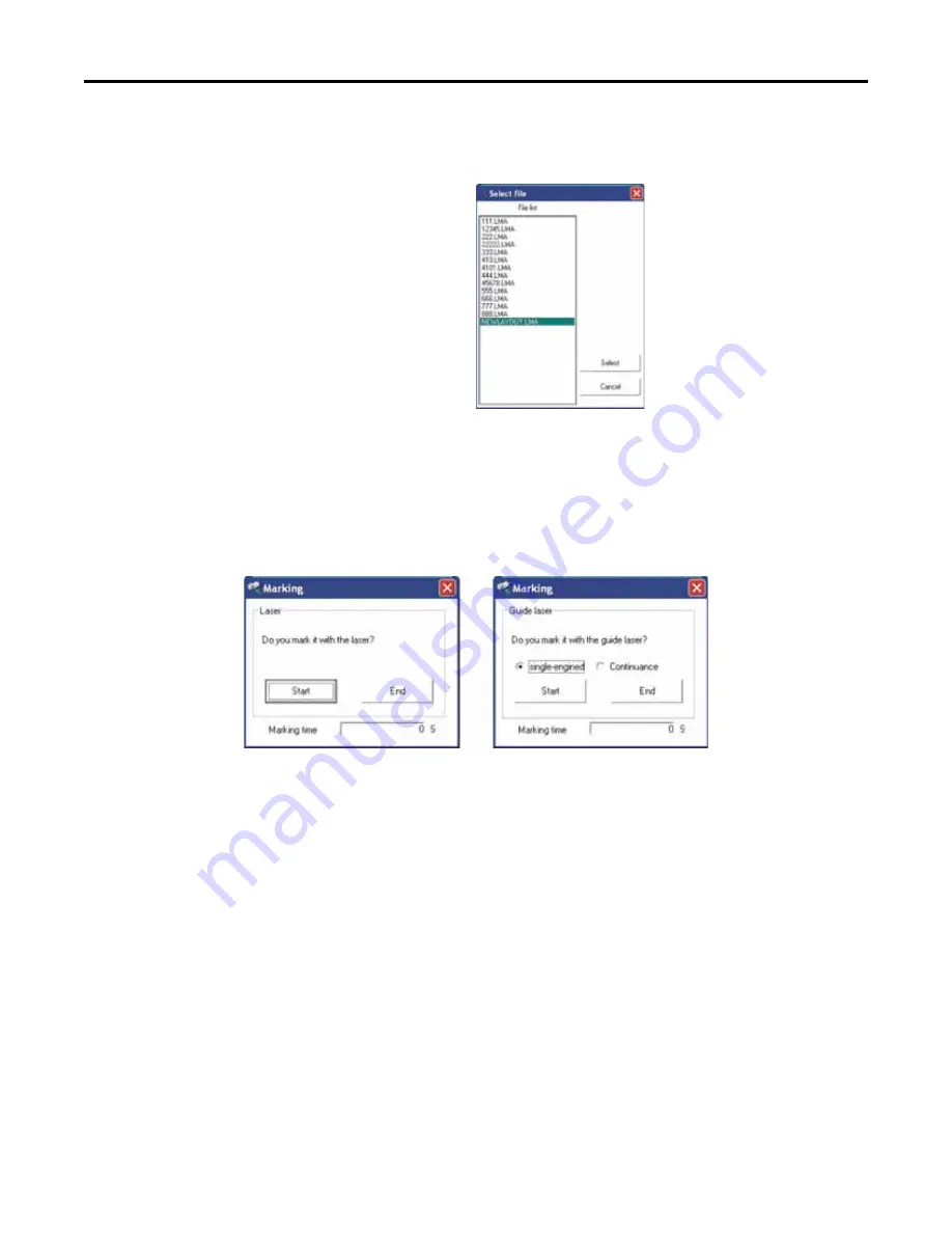
Select marking layout file
After pressing the
List
button to
display the
Select file
screen
shown on the right, click on a
desired file, then click on the
Select
button.
(The work folder file contents are
displayed here.)
ii.
Selection of laser or guide beam. Used to select laser or guide beam output (LMV1000(E)
& ML-7110A(-CE) only).
iii.
Marking instruction
Press
Marking
to display the marking instructions dialog box shown below. Select
single-
engined
(one-time) or
Continuance
(continuous), then press
Start
to execute the marking
process.
f.
Laser parameter setting
Click on the
Set
button to modify the laser parameters. Characters will display pink when
editing and white at the end of the data transfer.
g. Message
box
Displays
Marking in progress
and other system status displays.
h.
Unit status display
Displays the status of each unit.
A dithered figure indicates the section is off line.
A normal shaded figure indicates the section is on line and active.
Содержание LMV1000
Страница 8: ...LMV1000 G E AIR COOLED LASER MARKER viii 990 541...
Страница 9: ...LMV1000 G E AIR COOLED LASER MARKER 990 541 ix...
Страница 17: ......
Страница 35: ......
Страница 47: ......
Страница 215: ...8 COMMUNICATION FUNCTION OPTION LMV1000 G E AIR COOLED LASER MARKER 8 14 990 541...
Страница 231: ......
Страница 237: ......
Страница 238: ...LMV1000 G E AIR COOLED LASER MARKER 990 541 11 1 CHAPTER 11 OUTLINE DIMENSIONS 1 Dimensions Control Unit Oscillator...
Страница 239: ...11 OUTLINE DIMENSIONS LMV1000 G E AIR COOLED LASER MARKER 11 2 990 541 Oscillator Continued...
Страница 241: ...11 OUTLINE DIMENSIONS LMV1000 G E AIR COOLED LASER MARKER 11 4 990 541 Oscillator 1 2 3 4...
Страница 243: ......
Страница 259: ......


