UM_NX-W_00_05_19_ML
EN
MITSUBISHI ELECTRIC HYDRONICS & IT COOLING SYSTEM S.p.A.
42
Translation of the original instructions
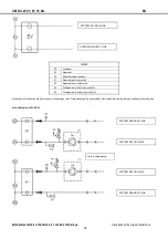
Pe
Evaporator circulation pump
SC
Discharge valve
SF
Relief valve
S1
Evaporator water inlet probe
S2
Evaporator water outlet probe
S3
Condenser water inlet probe
S4
Condenser water outlet probe
VA
Pressure relief valve
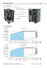
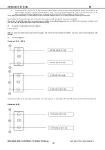
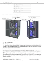
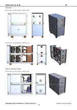
Position of air relief valves and safety valves on units with integrated hydronic kits.
NOTE: The maximum working pressure of the hydraulic circuit is 10 bar.
7
ELECTRICAL CONNECTIONS
7.1
Power supply
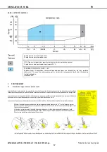
The specifications of the mains power supply must comply with EN 60204-1 and the local regulations in force and be sufficient for the absorption requirements of the unit indicated
in the wiring diagram and on the data plate. Mains voltage must correspond to the rated value +/- 10% with a maximum phase difference of 2%. The unit must be connection to
a three-phase TN(S) type electric power supply. Should the installation of a circuit breaker be envisaged in the electrical system, it must be type A or B. Its installation is obligatory
when it is indicated in the wiring diagram.
Refer to local bylaws. Only power the system if the hydraulic circuit is charged.
7.2
Power connections
Install an overload cut-out device, not included in the supply, on the supply line of the electrical panel in compliance with the regulations in force.
Connect the unit electrical panel with cables of a diameter suited to the absorption capacity of the machine indicated on the data plate and to the application. Tighten the eye lugs
at torques suited to the connections. Also observe any requirements indicated in the wiring diagram. The control circuit is shunted off the power circuit from inside the electrical
panel.
Do not touch hot and/or sharp surfaces. It is prohibited to insert wires in the electrical panel at any points other than the designated ones.
Before generating a vacuum in the cooling circuit, make sure to disconnect from the power supply all the phases of the electric motor of the compressors by removing or
disconnecting the electrical protections (fuses and/or automatic switch) upstream of the cooling circuit. The evaporating and condensing units with screw compressors are
delivered with the protections disconnected. After performing the refrigerant charge, put the protections back in place with the power turned off before start-up.
The supply must never be disconnected, except during maintenance operations, in order to guarantee operation of the compressor crankcase heater and any anti-freeze
resistances on the heat exchangers.
SAFETY VALVE
(10 BAR)
SAFETY VALVE
(10 BAR)
AIR RELIEF VALVE
AIR RELIEF VALVE

