UM_NX-W_00_05_19_ML
EN
MITSUBISHI ELECTRIC HYDRONICS & IT COOLING SYSTEM S.p.A.
38
Translation of the original instructions
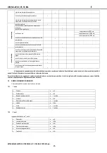
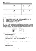
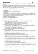
3
Chloride ions
Cl
-
< 150 ppm
4
Iron ions
Fe
3+
< 0.5 ppm
5
Manganese ions
Mn
2+
< 0.05 ppm
6
Carbon dioxide
CO
2
< 10 ppm
7
Hydrogen sulphide
H
2
S
< 50 ppb
8
Oxygen
O
2
< 0.1 ppm
9
Chlorine
Cl
2
< 0.5 ppm
10
Ammonia
NH
3
< 0.5 ppm
11
ratio between carbonates and sulphates
HCO
3-
/ SO
4
2-
> 1
Tab.5
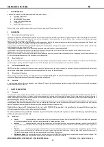
where:
1/1.78 °D=1 °Fr
with 1°Fr= 10 gr CaCO
3
/ m
3
ppm = parts per million; ppb = parts per billion
Explanatory notes
ref. 1:
A greater concentration of hydrogen ions (pH) than 9 implies a high risk of deposits, whereas a lower pH than 7 implies a high risk of corrosion
ref. 2:
The hardness measures the amount of Ca and Mg carbonate dissolved in the water with a temperature lower than 100 °C (temporary hardness).
A high hardness implies a high risk of deposits.
ref. 3:
The concentration of chloride ions with higher values than those indicated causes corrosion
ref. 4 - 5 - 8:
The presence of iron and manganese ions and oxygen leads to corrosion
ref. 6 - 7:
Carbon dioxide and hydrogen sulphide are impurities that promote corrosion
ref. 9:
Usually in water from the waterworks it is a value of between 0.2 and 0.3 ppm. High values cause corrosion
ref. 10:
The presence of ammonia reinforces the oxidising power of oxygen
ref. 11:
Below the value shown in the table, there is a risk of corrosion due to the trigger of galvanic currents between copper and other less noble metals.
In the case of service fluids other than water (e.g. ethylene or propylene glycol), it is advisable to always use fluids containing special inhibitors that offer thermal stability within
the operating temperature ranges and protection against corrosion phenomena.
It is absolutely essential that, in the presence of dirty and/or aggressive fluids, an intermediate heat exchanger is placed upstream of the refrigeration system heat exchangers.
The presence of air in the hydraulic circuit reduces the performance and can cause serious malfunctions and even defects, in particular to the pumping system and to the heat
exchangers. All the air must be released out of the air bleed valves of the unit and system and not allowed to enter again when setting up the hydraulic connection of the unit.
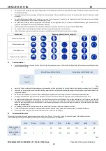
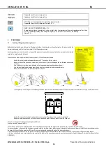
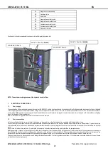
The inlet and outlet direction of the vector fluid in the heat exchangers is indicated by the following plates:
6.1
Evaporator / recuperator
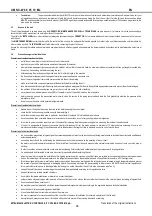
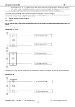
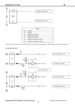
The following must be installed on the heat exchanger hydraulic circuit taking care to respect the correct positioning (see Fig. 1 page A1):
•
Two pressure gauges with a suitable range (inlet - outlet).
•
Two service cocks for the pressure gauges.
•
Air bleed valves to be fitted to the highest points of the circuit.
•
Two vibration damping joints (inlet - outlet) positioned horizontally.
•
One flow switch to be fitted at the unit outlet in a linear stretch of a length of about 7 times the diameter of the pipe itself. The flow switch must be calibrated so as
to guarantee a minimum water flow to the heat exchangers, not less than the value indicated in the unit bulletin or declared by the supplier. If this value is not
available, calibrate the flow switch to 70% of the rated water flow of the unit (not envisaged for desuperheaters).
•
A calibration valve at the outlet.
•
Two shut-off valves (inlet - outlet).
•
a two-way bypass valve, or a three-way mixing valve, to be used during start-up when the temperature of the water is too cold/hot
•
A mechanical filter with a maximum mesh size of 1 mm to be fitted as near as possible (maximum distance 2 metres) to the heat exchanger inlet
•
A drain cock to be fitted in the lowest point of the hydraulic system.
•
A circulation pump.
•
an expansion tank
•
a safety valve
•
• All other equipment listed in fig. 1 page A1.


