7 Setting the Position Detection System
MITSUBISHI CNC
134
(b)
Setting the reference position
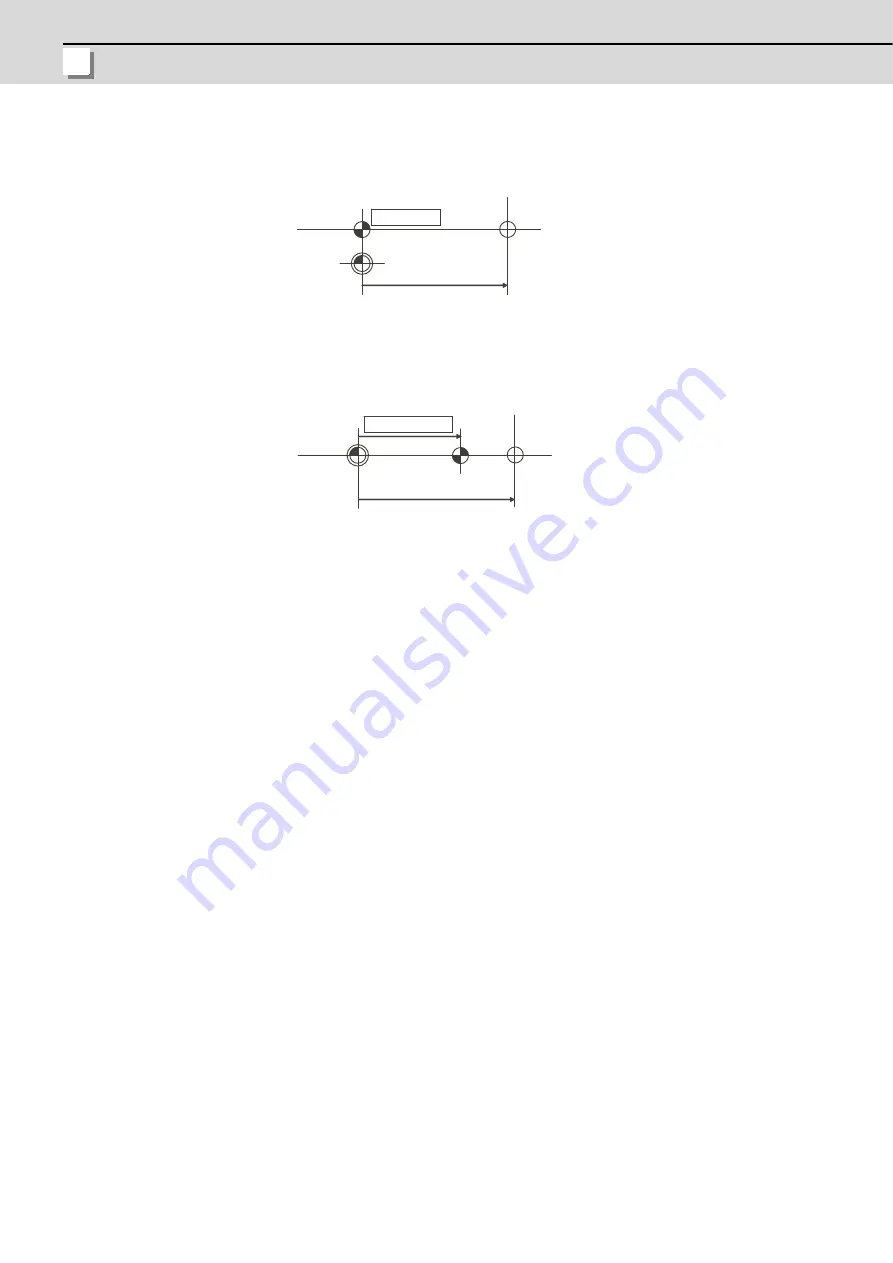
The reference position can be set as shown below by setting "#2037 G53ofs".
(Example 1)To set the reference position to the same position as the basic machine coordinate system zero point.
(Example 2)To set the reference point at a position 200.0mm to the + side from the basic machine coordinate zero
point. (To set the basic machine coordinate system zero point 300.0mm front of the absolute position
origin point.)
(c)
Common precautions for initialization operations
(1)
The "#0 INIT. SET" parameter (axis for which zero point is to be initialized) can be set simultaneously for all
axes or individually for each axis.
(2)
The "#0 INIT. SET" parameter cannot be turned OFF with the keys. It is turned OFF when the power is turned
ON again.
If this parameter is ON for even one axis, the message "INITIAL SET (ABS)" will appear in the operation status
display area of all screens, and "In zero point initialization" signal will be output for the axis.The automatic, MDI
and manual zero point return operations will be interlocked at this time.
(3)
"#2 Zero" can be set at any time as long as "#0 INIT. SET" is set to "1".
(4)
The grid point must be passed at least once after the power-ON for the zero point initialization. If no grid point
has been passed, "Not Pass" will appear at the "MACHINE" display.
(5)
The necessary data will be saved in EEROM upon the establishment of the absolute position. The message
notifies that the data is being written in EEROM.
Reference
position
Absolute position
basic point
Basic machine
coordinate system
zero point
"#2 ZERO"
"G53ofs" = 0
Basic machine
coordinate system
zero point
Absolute position
basic point
Reference
position
"G53ofs" = 200.0
"#2 ZERO" = 300.0
Содержание C70
Страница 1: ......
Страница 3: ......
Страница 9: ......
Страница 11: ......
Страница 13: ......
Страница 18: ...1 1 Outline ...
Страница 21: ...1 Outline MITSUBISHI CNC 4 ...
Страница 22: ...5 2 GOT Initial Setup ...
Страница 73: ...2 GOT Initial Setup MITSUBISHI CNC 56 ...
Страница 74: ...57 3 PLC CPU Initial Setup ...
Страница 91: ...3 PLC CPU Initial Setup MITSUBISHI CNC 74 ...
Страница 92: ...75 4 CNC CPU Initial Setup ...
Страница 105: ...4 CNC CPU Initial Setup MITSUBISHI CNC 88 ...
Страница 106: ...89 5 Connecting and Setting up Multiple CNC CPU Modules ...
Страница 115: ...5 Connecting and Setting up Multiple CNC CPU Modules MITSUBISHI CNC 98 ...
Страница 116: ...99 6 Setting Machine Parameters ...
Страница 130: ...113 7 Setting the Position Detection System ...
Страница 153: ...7 Setting the Position Detection System MITSUBISHI CNC 136 ...
Страница 154: ...137 8 Deceleration Check ...
Страница 159: ...8 Deceleration Check MITSUBISHI CNC 142 ...
Страница 160: ...143 9 Setting the Tool Entry Prohibited Range ...
Страница 169: ...9 Setting the Tool Entry Prohibited Range MITSUBISHI CNC 152 ...
Страница 170: ...153 10 Data Backup and Restoration ...
Страница 184: ...167 Appendix 1 Explanation of Parameters ...
Страница 435: ...Appendix 1 Explanation of Parameters MITSUBISHI CNC 418 ...
Страница 436: ...419 Appendix 2 Explanation of Alarms ...
Страница 608: ...591 Appendix 3 Display on 7 segment LED ...
Страница 624: ......
Страница 628: ......


