Image Optimization 5-29
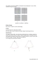
orientation. The blue plane shows the image acquisition where started, while the red
plane shows the image acquisition where ended. A yellow plane in the wire cage shows
the position of the MPR. See the image below:
Wire Cage
5.10.2 Note Before Use
5.10.2.1 3D Image Quality Conditions
NOTE:
In accordance with the ALARA (As Low As Reasonably Achievable) principle, try to
shorten the sweeping time after a good 3D image is obtained.
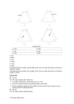
Angle of a B tangent plane
The optimum tangent plane to the face 3D imaging is the sagittal section of the face. To
ensure high image quality, scan the maximum face area and maintain edge continuity.
Image quality in B mode (2D image quality)
Before entering 3D capture, optimize the B mode image to ensure:
High contrast between the desired region and the surrounding AF.
Clear boundary of the desired region.
Low noise of the AF area.
Scanning technique (only for Smart 3D)
Stability: the body, arm and wrist must move smoothly, otherwise the restructured 3D
image distorts.
Slowness: move or rotate the probe slowly.
Evenness: move or rotate the probe at a steady speed or rate.
NOTE:
1. A region with a qualified image in B mode may not be optimal for 3D imaging.
E.g., adequate AF isolation for one MPR does not mean the whole desired
region is isolated by AF.
2. Practice is needed for a high success rate of qualified 3D imaging.
5.10.3 Smart 3D
The operator manually moves the probe to change its position/angle when performing the
scan. After scanning, the system carries out image rendering automatically, then displays a
frame of the 3D image.
Smart 3D is an option.
5.10.3.1 Basic Procedures for Smart 3D Imaging
NOTE:
In Smart 3D image scanning, if the probe orientation mark is oriented to the
operator’s finger, perform the scan from right to left in linear scan, or rotate the
probe from left to right in rocked scanning. Otherwise, the VR direction will be
wrong.
To perform Smart 3D imaging:
1. Select the appropriate probe and exam mode. Make sure there is sufficient gel on the
probe for scanning.
Содержание DP-50 Exp Vet
Страница 2: ......
Страница 34: ...2 6 System Overview 2 6 Introduction of Each Unit Right View Left View...
Страница 42: ......
Страница 68: ......
Страница 128: ......
Страница 148: ......
Страница 166: ...10 18 DICOM For details on tast manager see 9 6 Animal Task Manager...
Страница 180: ......
Страница 220: ......
Страница 224: ......
Страница 236: ......
Страница 242: ......
Страница 248: ......
Страница 249: ...Acoustic Output Reporting Table 60601 2 37 C 1 Appendix C Acoustic Output Reporting Table 60601 2 37...
Страница 342: ...D 2 Printer Adapter Type Model SONY X898MD...
Страница 343: ...P N 046 017713 02 1 0...


