5-20 Image Optimization
4. Press the user-defined key for the PW mode or <Update> to enter PW mode again and
perform the examination. You can also adjust the SV size, angle and depth in real-time
scanning.
5. Adjust the image parameters during PW mode scanning to obtain optimized image.
6. Perform other operations (e.g. measurement and calculation) if necessary.
5.8.2
PW Mode Image Parameters
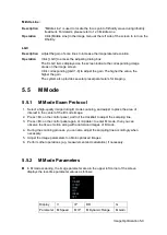
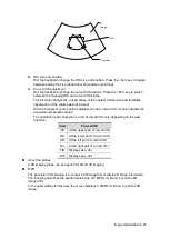
In PW mode scanning, the image parameter area in the upper right corner of the screen
displays the real-time parameter values as follows:
Parameter
F
G
PRF
WF
SVD
SV
Angle
Meaning
Frequency
Gain
PRF
Wall Filter
SV Position
SV Size
Angle
When you adjust the depth of the B mode image, related changes will occur in PW mode
image as well.
5.8.3
PW Mode Image Optimization
Gain
Description
This function is intended to adjust the gain of spectrum map. The real-time
gain value is displayed in the image parameter area in the upper right corner
of the screen.
Operations
Rotate the [Gain/iTouch] knob to adjust the gain.
The adjusting range is 0-100.
Effects
Increasing the gain will brighten the image and you can see more received
signals. However, noise may also be increased.
Frequency
Description
Refers to the operating frequency in PW mode of the probe, the real-time value
of which is displayed in the image parameter area in the upper left corner of
the screen.
Operation
Select the frequency value through the [Frequency] item in the image menu or
rotate the <Focus/Freq./THI> knob on the control panel.
Values of frequency vary depending upon the probe types.
Select the frequency according to the detection depth and current tissue
characteristics.
Effects
The higher the frequency, the better the resolution and sensitivity, and the
worse the force of penetration.
A. power
Description
Refers to the power of ultrasonic wave transmitted by the probe, the real-time
value of which is displayed in the image parameter area in the upper left corner
of the screen.
Operation
Adjust through the [Acoustic Power] item in the image menu;
The adjusting range is 0%-100% and the adjusting level is 32.
Содержание DP-50 Exp Vet
Страница 2: ......
Страница 34: ...2 6 System Overview 2 6 Introduction of Each Unit Right View Left View...
Страница 42: ......
Страница 68: ......
Страница 128: ......
Страница 148: ......
Страница 166: ...10 18 DICOM For details on tast manager see 9 6 Animal Task Manager...
Страница 180: ......
Страница 220: ......
Страница 224: ......
Страница 236: ......
Страница 242: ......
Страница 248: ......
Страница 249: ...Acoustic Output Reporting Table 60601 2 37 C 1 Appendix C Acoustic Output Reporting Table 60601 2 37...
Страница 342: ...D 2 Printer Adapter Type Model SONY X898MD...
Страница 343: ...P N 046 017713 02 1 0...


