background image

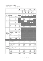
  Acoustic Output Reporting Table (60601-2-37) C-91 

Transducer Model: 75L50EAV 

Imaging Mode:        Color+B-Mode / Power+B-Mode         


Index label 

MI 

TIS 

TIB 

TIC 


At 

surfac

Below 
surfac

At 

surfac

Below 
surfac


Maximum index value 

0.98 

0.17 

0.17 

0.40 

Index component value 


0.17 

0.17 

0.17 

0.17 


Acoustic 

Parameter

p

r,

α

 at 

z

MI 


(MPa)


2.31 


P


(mW)


28.00 

28.00 

28.00 

P

1×1   

                        (mW)


5.83 

5.83 


z

s

                                (cm)


z

b                                         

(cm)


z

MI


(cm)


1.18 


z

pii

,

α


(cm)


1.18 


f

awf


(MHz)


5.59 

6.81 

6.81 

5.93 

Other 

Information 

prr


(Hz)


2,642.00 


srr


    (Hz)


47.00 


n

pps


I

pa,

α

 at 

z

pii

,

α                       

(W/cm

2

)


209.16 


I

spta,

α

 at 

z

pii

,

α

 or 

z

sii

,

α   

(mW/cm

2

)


18.95 


I

spta

 at 

z

pii

 or 

z

sii   


(mW/cm

2

)


29.90 


p

r

 at 

z

pii


(MPa)


2.90 


Operating 

control 

conditions 

Acoustic power   

100% 

100% 

100% 

100% 

Display depth 

16.6cm 

16.6cm 

16.6cm 

16.6cm 

B Focus Position 

1.5cm 

8.0cm 

8.0cm 

7.0cm 

Color 

Sampling 

Gate 

Position 

1.5cm 

8.0cm 

8.0cm 

7.0cm 

B Working Frequency 

C Working Frequency 

B PRF 

802 

1605 

1605 

1605 

Color PRF 

2642 

3498 

3498 

3498 


Содержание DP-50 Exp Vet

Страница 1: ...DP 50 Vet DP 70 Vet DP 50 Exp Vet Digital Ultrasonic Diagnostic Imaging System Operator s Manual Basic Volume...

Страница 2: ......

Страница 3: ...aning of Signal Words 1 2 1 3 Meaning of Safety Symbols 1 2 1 4 Safety Precautions 1 3 1 5 Latex Alert 1 11 1 6 Warning Labels 1 12 2 System Overview 2 1 2 1 Intended Use 2 1 2 2 Contraindication 2 1...

Страница 4: ...ideo Printer 3 8 3 9 Analog Video Printer 3 9 3 10 External DVD 3 9 3 11 Basic Screen and Operation 3 10 3 11 1 Basic Screen 3 10 3 11 2 Basic Operations of Screens 3 13 4 Exam Preparation 4 1 4 1 Sta...

Страница 5: ...r Mode Image Optimization 5 17 5 7 1 Basic Procedures for Power Mode Imaging 5 18 5 7 2 Power Mode Image Parameters 5 18 5 7 3 Power Mode Image Optimization 5 18 5 8 PW Doppler Mode 5 19 5 8 1 Basic P...

Страница 6: ...2D General Measurements 7 2 7 2 2 M General Measurements 7 2 7 2 3 Doppler General Measurements 7 3 7 3 Application Measurement 7 3 7 4 Measurement Accuracy 7 4 8 Comments and Body Marks 8 1 8 1 Comm...

Страница 7: ...Animal 9 11 9 4 2 Animal Data View Management 9 12 9 5 Backing Up and Erasing Files through DVD Drive 9 14 9 6 Animal Task Manager 9 14 9 7 Access Control 9 16 9 7 1 Access Setting 9 16 9 7 2 Setting...

Страница 8: ...12 11 8 2 Other Settings 11 13 11 9 System Information 11 13 12 Probes and Biopsy 12 1 12 1 Probe 12 1 12 1 1 Name and Function of Each Part of the Transducer 12 3 12 1 2 Orientation of the Ultrasoun...

Страница 9: ...TI Explanation 14 2 14 4 1 Basic Knowledge of MI and TI 14 2 14 4 2 MI TI Display 14 3 14 5 Acoustic Power Setting 14 3 14 6 Acoustic Power Control 14 4 14 7 Acoustic Output 14 4 14 7 1 Derated Ultra...

Страница 10: ...viii Appendix B Transducer Maximum Surface Temperature B 1 Appendix C Acoustic Output Reporting Table 60601 2 37 C 1 Appendix D Printer Adapter D 1...

Страница 11: ...ts or copyright of Mindray or of others Mindray intends to maintain the contents of this manual as confidential information Disclosure of the information in this manual in any manner whatsoever withou...

Страница 12: ...ry out a reasonable service maintenance plan Neglect of this may result in machine breakdown or personal injury Warranty THIS WARRANTY IS EXCLUSIVE AND IS IN LIEU OF ALL OTHER WARRANTIES EXPRESSED OR...

Страница 13: ...burg 20537 Germany Tel 0049 40 2513175 Fax 0049 40 255726 Manufacturer Shenzhen Mindray Bio Medical Electronics Co Ltd Address Mindray Building Keji 12th Road South High tech industrial park Nanshan S...

Страница 14: ...software or hardware of this system 5 In no event shall Mindray be liable for problems damage or loss caused by relocation modification or repair performed by personnel other than those designated by...

Страница 15: ...e operator s manuals carefully before operating the system The content of the operator manual such as screens menus or descriptions may be different from what you see in your system The content varies...

Страница 16: ...x The square bracket indicates items in menu or buttons in dialog box Click Items or Button Move the cursor to the item or button and press Set or click it on the menu Items in Menu Items in Submenu S...

Страница 17: ...he degree of protection against harmful ingress of water Main unit IPX0 Probes IPX7 Footswitch IP68 According to the degree of safety of application in the presence of a FLAMMABLE ANESTHETIC MIXTURE W...

Страница 18: ...serious injury CAUTION Indicates a potentially hazardous situation that if not avoided may result in minor or moderate injury NOTE Indicates a potentially hazardous situation that if not avoided may r...

Страница 19: ...ctive grounding conductor before turning ON the system Disconnect the grounding cable after turning OFF the system Otherwise electric shock may result 3 For the connection of power and grounding follo...

Страница 20: ...the system from other devices including probes and disconnect the system from the power supply 14 Accessory equipment connected to the analog and digital interfaces must comply with the relevant IEC s...

Страница 21: ...sound system use a mains plug as isolation means to the mains power supply Please do not set the ultrasound system in a place difficult to operate the mains plug 20 Do not modify this equipment withou...

Страница 22: ...have to move the system with the mobile trolley upward or downward the stairs you must separate them first and then move them individually Object placed on the monitor may fall and injure an individu...

Страница 23: ...l data may be combined with the previous animal data 11 DO NOT connect or disconnect the system s power cord or its accessories e g a printer without turning OFF the power first This may damage the sy...

Страница 24: ...ay be lost due to system failure improper operation or accident 8 Do not apply external force to the control panel otherwise the system may be damaged 9 If the system is used in a small room the room...

Страница 25: ...examination CAUTION 1 When using the probe wear sterile gloves to prevent infection 2 Be sure to use ultrasound sterile gel Please use the ultrasound gel compliant with the relevant local regulations...

Страница 26: ...each examination After the examination wipe off the ultrasound gel thoroughly Otherwise the ultrasound gel may solidify and the image quality would be degraded After an examination wipe the ultrasound...

Страница 27: ...following CIVCO Medical Instruments Tel 1 800 445 6741 WWW civco com WARNING Allergic reactions in latex natural rubber sensitive animals may range from mild skin reactions irritation to fatal anaphyl...

Страница 28: ...nd meaning of each warning label are described as follows No Warning Labels Meaning 1 Please carefully read this manual before use device 2 The following label is available when the system works with...

Страница 29: ...examination and diagnosis 2 2 Contraindication None 2 3 Product and Model Code NOTE The functions described in the operator s manual may vary depending upon the specific system you purchased 2 4 Prod...

Страница 30: ...060hPa 2 4 4 Size and weights Size 147 5mm 361 5mm 358 5mm Depth Width Height Net Weight 8 1 0 5kg without battery two probe ports 2 5 System Configuration 2 5 1 Standard Configuration Main unit Syste...

Страница 31: ...bes have matched needle guided brackets for biopsy the available probes and the corresponding needle guided brackets are listed as follows Probe Model Needle guided Bracket Model Biopsy Angle Depth 1...

Страница 32: ...0G 22G 2 5 3 Options No Item 1 IMT 2 DICOM Module DICOM basic including Connection Verification Task Management DICOM storage DICOM print DICOM storage commitment DICOM media storage including DICOM D...

Страница 33: ...only for CE region WARNING This system complies with IEC60601 1 2 2014 and its RF emission meets the requirements of CISPR11 Class B In a domestic environment the customer or the user should guarante...

Страница 34: ...2 6 System Overview 2 6 Introduction of Each Unit Right View Left View...

Страница 35: ...ol Panel Refer to 2 6 3 Control Panel 4 USB ports Used to connect USB devices 5 Handle Used to carry the machine 6 I O Panel Interface panel used for inputting and outputting signals refer to 2 6 1 I...

Страница 36: ...nnecting video printer or LCD 5 Remote control port 6 VGA VGA signal output 7 Composite video output 8 Power indicator 2 6 2 Power Supply Panel No Name Function 1 Power inlet AC power inlet 2 Equipote...

Страница 37: ...Press to exit the current status to the previous status 3 Help Press to display or hide the help information on screen 4 Patient Animal Information Press to open exit animal information screen 5 Prob...

Страница 38: ...ss or contrast when pressing with Fn key 19 Cine Press to enter or exit the cine review status 20 Body Mark Press to enter or exit the Body Mark status 21 Arrow Press to enter or exit the arrow commen...

Страница 39: ...ess to save user defined key 43 Save 2 Press to save user defined key 44 Freeze Press to freeze or unfreeze the image 45 Print Press to print user defined key 46 Indicator 1 AC indicator AC supply lig...

Страница 40: ...e BF applied part Caution Dangerous voltage Equipotentiality Power button Network port USB ports Video output Remote control port VGA VGA signal output AC Alternating current Battery Status Indicator...

Страница 41: ...System Overview 2 13 Symbol Description The device is fully in conformance with the low voltage directive 2014 35 EU and the EMC directive 2014 30 EU...

Страница 42: ......

Страница 43: ...lted due to increased system operating temperature 3 2 Power Supply This system can work normally only when it is connected to the external power supply or the battery capacity is sufficient 3 2 1 Con...

Страница 44: ...mental Conditions for details 2 There shall be no condensation 3 There shall be no distortion damage or dirt on the system and peripheral devices If any dirt is found cleaning shall be performed as de...

Страница 45: ...rn the animal 2 If you find anything not functioning properly this may indicate that the system is defective In this case shut down the system immediately and contact Mindray Customer Service Departme...

Страница 46: ...ting or disconnecting a probe place it in a proper position to prevent the probe from falling off or becoming damaged 2 Only use the probes provided by Mindray Aftermarket probes may result in damage...

Страница 47: ...e Device WARNING DO NOT detach an USB storage device directly otherwise the ultrasound system or the USB device and or data stored in the device may be damaged When connecting a USB storage device to...

Страница 48: ...he printer status Enter Setup Print Preset Printer Driver page printers that are installed automatically will be displayed in the list with the Status of Ready 5 Return to Print Service page and selec...

Страница 49: ...storage device USB disk as an example b Connect the USB disk to the ultrasound system click Setup Print Preset Printer Driver Add Local Printer to run the ppd file and finish the installation NOTE Al...

Страница 50: ...rinter IP address with Ready status 2 Click Print Service to enter the screen and select AssistPrinter IP address to be the printer for the Report Print service 3 Click Save Print Service You can use...

Страница 51: ...accompanying manuals of the printers for more details 3 9 Analog Video Printer 1 Connect the printer VIDEO IN port and the ultrasound system S Video on IO panel with the signal cable 2 Connect the Re...

Страница 52: ...ime acoustic power MI TI freeze icon animal information probe model current exam mode and accession etc It can be preset whether to display the operator animal gender age ID name etc via Setup System...

Страница 53: ...d in hospital information system It can be imported via DICOM or input manually Menu area Include image menu measurement menu comment menu bodymark menu and so on Use the trackball or the multifunctio...

Страница 54: ...coordinate axis including depth time velocity frequency focus position located at depth axis in the form of besides the annotation bodymark measurement calipers grayscale bar are also displayed here T...

Страница 55: ...s Set again to anchor the result window in the target position Comment area For details please refer to 8 Comments and Body Marks Body mark area For details please refer to 8 Comments and Body Marks 3...

Страница 56: ...ow the list and select an item Save and Cancel When the operation of a screen is complete press the Save or Cancel button to save or cancel the operation and close the screen To reposition a dialogue...

Страница 57: ...paused within 24 hours and continue the exam with the imported animal information and exam data For details please refer to 4 5 Activate Continue an Exam General procedure for an exam enter the anima...

Страница 58: ...ame Enter animal name through the keyboard Characters of A through Z and 0 through 9 and are allowed and are not permitted Animal ID Animal ID is generated automatically by the system after starting a...

Страница 59: ...mat as that of the system 2 Exam Type Exam application type You can select among ABD Abdomen REP reproduction CARD Cardiac VAS Vascular and SMP Small Part Select the exam type tab to enter the exam sp...

Страница 60: ...rine pregnancy Gestations Number of embryos 1 2 3 1 is default Para Times of delivery Aborta Times of abortion CARD Cardiac Height Weight BSA body surface area After the height and weight are inputted...

Страница 61: ...n enter the searching conditions for the animal 1 To enter iStation screen the screen is shown as follows Press iStation on the control panel or Click iStation in the Animal Info screen or Press the R...

Страница 62: ...ried out within 24 hours Other buttons New Exam Click to enter Animal Info screen meanwhile the corresponding animal information is also imported to the new exam After you edit the animal information...

Страница 63: ...to start a new exam Click Show Detail to see details of animal data 4 Click Exit to exit the Worklist 4 3 Select Exam Mode and Probe CAUTION If the exam mode is changed during a measurement all measu...

Страница 64: ...reset user defined key to implement switching probes between single B and 2B mode The function is only available to the probes of the same exam mode In single B mode press the user defined key to swit...

Страница 65: ...0EA to the ultrasound system 2 Press Setup to enter the setup screen select System Preset Key Config to enter the page 3 Select the user defined key in the Key Function page on the left or select the...

Страница 66: ...am paused within 24 hours select the exam record in iStation screen click from the menu popped up to continue the exam If you want to continue an exam which data lies in an external memory database yo...

Страница 67: ...ion to avoid mixing data of the next new animal To end an exam you can do one of the following Press End Exam on the control panel Click New Animal on the Animal Info screen to end the last animal exa...

Страница 68: ......

Страница 69: ...Panel 5 2 Basic Operations Before optimizing the image by adjusting image parameters adjust the brightness and contrast of the display to the best Requirement Available Operations To modify the bright...

Страница 70: ...after the Save As to assign a name for a user defined exam mode and click Create to save the current image parameters measurements comments body mark settings to the exam mode Restore factory setting...

Страница 71: ...of the screen Operation Rotate the Gain iTouch knob clockwise to increase the gain and anticlockwise to decrease The adjusting range is 0 100 Effects Increasing the gain will brighten the image and yo...

Страница 72: ...ects The higher the frequency the better the near field resolution but the worse the force of penetration Harmonic imaging enhances near field resolution and reduces low frequency and large amplitude...

Страница 73: ...zoid or ExFov functions via Setup System Preset Key Config B Steer This function is to steer the beam transmitted by the probe Steer the transmitting beam through the B Steer item in the menu The stee...

Страница 74: ...Rotation Invert Description This function provides a better observation for image display Invert To invert the image horizontally or vertically Click L R Flip or U D Flip in the menu to invert the im...

Страница 75: ...n the upper left corner of the screen The IP combination parameters include dynamic range iClear persistence and smooth Operation Select among the IP groups through the IP item in the menu The system...

Страница 76: ...distortion of images Operation Click on the image menu to adjust The adjusting range is 0 3 increase the value the image turns dark Gray Invert Description Reverse the polarity of the image Operation...

Страница 77: ...arameters for imaging 5 5 M Mode 5 5 1 M Mode Exam Protocol 1 Select a high quality image during B mode scanning and adjust to place the area of interest in the center of the B mode image 2 Press M on...

Страница 78: ...justable depth values vary depending upon the probe types Effects Increase the depth to see tissue in deeper locations while decrease the depth to see tissue in shallower locations Impacts Depth incre...

Страница 79: ...rmat Description To set the display format of M mode image with B mode image Operation Adjust through the Display Format item in the menu There are 4 formats available for the images display V2 1 V1 1...

Страница 80: ...the dialogue box to adjust Drag the curve node to increase or decrease the gray scale information drag the node up to increase the information and down to decrease Description The correction is used t...

Страница 81: ...s displayed on the image parameter area in the upper left corner of the screen Operation Adjust through the Dyn Ra item in the menu The adjusting range is 30 220dB in increments of 5dB Effects The mor...

Страница 82: ...corner of the screen displays the real time parameter values as follows Parameter F G PRF WF Meaning Frequency Color Gain Pulse Repetition Frequency PRF Color Wall Filter In Color Mode acoustic power...

Страница 83: ...left to adjust The adjusting range varies by frequency probe and depth adjust according to the actual situation Effects To provide a much clearer color flow image Use low PRF to observe low velocity f...

Страница 84: ...te changing Persistence Description This function is to adjust the temporal smooth in Color mode to optimize the image Operations Click the Persistence item on the image menu The system provides 0 4 l...

Страница 85: ...the line density the higher the resolution Impacts The higher the line density the lower the frame rate ROI Adjustment Description This function is to adjust the width and position of ROI in Color mo...

Страница 86: ...ower is synchronous with that of B mode Adjustment of the depth to the B mode image will lead to corresponding changes in Power mode image Parameters consistent with those in Color mode and B mode are...

Страница 87: ...s thus enhances the range of signals to display 5 8 PW Doppler Mode PW Pulsed Wave Doppler mode is used to provide blood flow velocity and direction utilizing a real time spectral display The horizont...

Страница 88: ...screen Operations Rotate the Gain iTouch knob to adjust the gain The adjusting range is 0 100 Effects Increasing the gain will brighten the image and you can see more received signals However noise m...

Страница 89: ...o set the display manner of spectrum Operations Turn on or off the function through the Invert item on the image menu Scale Description This function is used to adjust the speed range of flow which is...

Страница 90: ...scan speed available the smaller the value the faster the speed Effects Changing the speed makes it easier to identify the cardiac cycles and to detect more details Display Format Description To set t...

Страница 91: ...c Param on the image menu Auto Calc Cycle To set the number of heart cycle for auto calculation Click Auto Calc Cycle on the image menu to select the cycle number The adjustment range is 1 5 Operation...

Страница 92: ...e compare the image with that of other machines or make diagnosis using none ultrasound methods For an image in the traditional M mode the M mark line goes along the beams transmitted from the probe T...

Страница 93: ...ions Press Set to hide or show between the M mark lines and press Cursor to show the cursor The activated M mark line will be green Adjustment of the M mark Line Description To adjust the position and...

Страница 94: ...me data 3D image MultiPlaner Rendering MPR the three sectional planes of the volume acquisition As shown in the figure below the XY paralleled plane is the C section the XZ paralleled plane is the B s...

Страница 95: ...nt is displayed on the curved VOI it can be adjusted in acquisition preparation status The orientation and shape line or dot of curved VOI vary depending on the view direction View Curved VOI U D At t...

Страница 96: ...n the probe If the posture is head down toward the mother s feet and the orientation mark is toward the mother s head then the fetus posture is head down in the 3D image The 3D image can be rotated by...

Страница 97: ...Stability the body arm and wrist must move smoothly otherwise the restructured 3D image distorts Slowness move or rotate the probe slowly Evenness move or rotate the probe at a steady speed or rate N...

Страница 98: ...3D 4D key or user defined key for 3D to exit Smart 3D 5 10 3 2 Smart 3D Acquisition Preparation In Smart 3D mode you need to set the scan method Method Capture images using Linear scan or Rocked scan...

Страница 99: ...or tissues with tumors Method Function select the image acquisition method Selection Rocked Linear Linear mode during the sweep the probe must be kept parallel The scanning speed should be constant R...

Страница 100: ...enter image viewing The system enters image viewing when image acquisition is complete Exit To return to 3D image acquisition preparation status press Update or Freeze Activate MPR Select Current Wind...

Страница 101: ...ected the system displays the 3D image VR only View Direction The Region of Interest ROI also referred to as the Render Box in rendering contains the section of the volume you want to render Therefore...

Страница 102: ...ct Direction to be D U R L or B F on the menu to select the direction of the above Figure b d and f Adjust VOI VOI On The VR image displays VOI information 1 In image viewing status select VOI to turn...

Страница 103: ...re as follows Parameter Description Threshold Function to set the threshold for VR rendering The VR is rendered using the signal between the high and low thresholds When signals are received from smal...

Страница 104: ...tures Min Function set Min as the VR rendering mode Displays the minimum echo intensity in the observation direction This is useful for viewing vessels and hollow structures X ray Function set X ray a...

Страница 105: ...the current active plane so as to get a better view of VR Comments and Body Marks Function Add comments and body marks to the MPR and VR Operation The operation is the same as adding comments and body...

Страница 106: ...ered image edit mode Section image MPR measurement 2D related measurements can be performed on MPR For details see Advanced Volume Measurement is not available in acquisition preparation status 5 10 3...

Страница 107: ...ape mode Smooth even speed will help produce optimal image results Tips iScape is an optional module The display of the biopsy guideline is not allowed in iScape mode 5 11 1 Basic Procedures for iScap...

Страница 108: ...ut the probe speed during image slicing the system gives feedbacks about the probe moving speed in the form of color and words the relations are listed as follows Status ROI Color Tips Speed too low B...

Страница 109: ...ed image Press the Depth Zoom knob again to exit the zoom mode When image displayed is bigger than the image area the thumbnail is automatically displayed 5 11 3 3 Rotating the Image For the convenien...

Страница 110: ...anoramic image on the left side of screen In cine review status Roll the trackball to review the captured images frame by frame Click Auto Play to start or end auto play In auto play mode click Auto P...

Страница 111: ...s the frame rate which tends to change thermal indices The position of the focal zones may also change which may cause the peak intensity to occur at a different location in the acoustic filed As a re...

Страница 112: ...he setting 2 Open the image or the under scanning image press the user defined iZoom key once to zoom in the standard image area and then press the key again to zoom in the image area only 3 Press the...

Страница 113: ...litting modes Press B button on the control panel to enter the single display format which displays the currently activated window In single display format press Dual or Quad to switch between dual sp...

Страница 114: ...reversed to the image storing sequence thus the images are displayed in descending order Whereas if you roll the trackball to the right the review sequence is the same as the image storing sequence th...

Страница 115: ...lay the cine images on the screen one by one Roll the trackball to the left the review progress slider moves to the left the images moves to the right and the earlier stored images are invoked Whereas...

Страница 116: ...or the same patient a Select different exams in iStation screen select Review in the popped up menu to enter Review screen b In Review screen click History to select the exam click to select the image...

Страница 117: ...ory Clear In the following conditions the cine review memory will be cleared Start an exam of a new animal Start a new exam for the same animal Switching the probe if the cine memory is split only the...

Страница 118: ...pare to enter image compare mode 5 Review images from different image windows Press the Dual or Quad key to switch the active image window The window with the highlighted M mark is the currently activ...

Страница 119: ...ion measurement data are stored in the report 2 If the system is turned off or End Exam is pressed during a measurement the data not saved will be lost 3 In Dual B imaging mode the measurement results...

Страница 120: ...Measures the length of two line segments which are perpendicular to each other Distance Ratio Measures the lengths of any two line segments and the calculated ratio Area Ratio The areas of any two reg...

Страница 121: ...e measured Acceleration Velocity and time interval between two points are measured to calculate speed difference and acceleration D Trace On the PW mode image one or several Doppler waveforms are trac...

Страница 122: ...5 Other probe within 10 Table 2 Volume Measurements Parameter Value Range Error Volume Full screen Within 10 or when the measured value is less than 64 cm3 the error is less than 6 4 cm3 Table 3 Time...

Страница 123: ...status Tips when the system entered comment status the default characters entered are uppercase You can see the Caps Lock indicator lights on 2 Place the cursor to the desired place to set the comment...

Страница 124: ...with comment text libraries including Abdomen Cardiology GYN Gynecology OB Obstetrics Urology SMP Small Part Vascular PED Pediatric and Nerve Blocks Typing comment characters 1 To set the comment loca...

Страница 125: ...comment in the new position and the comment moving operation is complete 8 1 5 Editing Comments Modifying Editing characters 1 Move the cursor onto the comment that needs to be modified Directly ente...

Страница 126: ...and transducer position and orientation The system supports body marks for Dog Cat Equine Bovine Ovine or Other You can preset the system configured general body marks for each exam mode also you can...

Страница 127: ...c to any desired position within the image area 1 Roll the trackball to move the cursor onto the body mark The cursor changes into indicating you can move the pictogram to a new position 2 Press Set k...

Страница 128: ......

Страница 129: ...y is not responsible for lost data if you DO NOT follow suggested backup procedures 9 1 Animal Information Management 9 1 1 Enter Animal Information The general animal information and exam information...

Страница 130: ...ormat you can perform manual or auto cine review and perform measurements or add comments for the reviewed images After you open a stored CIN file the system automatically enters cine review status Th...

Страница 131: ...en in the BMP format To save cineloop image in the system 1 Enter Setup System Preset Key Config Output set a user defined key for function Save cine 2 Freeze an image Click the user defined key to sa...

Страница 132: ...In the iStation screen the thumbnails refer to the images stored for the selected exam or the selected animal In the scanning or freeze mode the thumbnails refer to the images stored in the current ex...

Страница 133: ...an select one certain exam from the exam directory to review the images If entered from iStation the screen displays the record s selected in the iStation If no animal is selected when it was in iStat...

Страница 134: ...the same as those for real time scanning please refer to relevant sections for details To enter image analysis In the image scanning or freeze status double click a thumbnail stored in this exam to e...

Страница 135: ...Catalog Demo Catalog demo catalog is the folder in hard disk E disc where the factory DEMO is stored The system plays the images in this folder when performs demonstration The system supports import...

Страница 136: ...tion screen click or in Review screen click Send To to send the selected image to the external devices See the figure below For external memory devices e g USB memory devices DVD iStorage server or Me...

Страница 137: ...port In the iStation screen select animal data click Restore or Backup to import or export animal information images and reports from or to an external memory device See the following figure In the iS...

Страница 138: ...about default report printer setting For details on report relevant operations please refer to Advanced Volume 9 4 Animal Data Management iStation The animal data include basic animal information exa...

Страница 139: ...u can select a new exam mode and click OK to begin a new exam Select All Exams Deselect All Exams Click Select All Exams to select all animal data listed Then the button changes into Deselect All Exam...

Страница 140: ...animal information of this exam Report After you select an exam of an animal click to view the report of this exam for this animal If no report is generated in the exam the system prompts that There...

Страница 141: ...st allow the system to load the animal data to the system s animal database Continue Exam Select an exam that is paused within 24 hours click to activate the exam and load the basic animal information...

Страница 142: ...symbol to pop up the Disc Option screen as shown in the figure below 3 Click Erase to erase data from a CD DVD 4 After the erasing process is completed click Eject in the Disc Option dialogue box Note...

Страница 143: ...Task List of the current printing task Displays the file name status printing or suspended printer name submit time etc If all print tasks are finished the print icon will disappear from the screen if...

Страница 144: ...tem administrator can view all animal data such as animal information image and report etc Operator The operator can only view the exam information saved in the system and operated by himself or herse...

Страница 145: ...ialogue box 2 Select the user name in the drop down list of User Name 3 Enter password and click Login For emergency users click Emergency directly to log on Changing user 1 To log out the current use...

Страница 146: ...r 6 Click OK to confirm the setting and exit the dialogue box then the new user will appear on the User List 9 7 4 2 Delete a User Premise you must login the system as the system administrator If not...

Страница 147: ...Setup System Preset Admin 2 Select the user name to be modified except emergency operator in User List click Change Password 3 Enter new password and confirm password in the dialog then click OK Sessi...

Страница 148: ......

Страница 149: ...ge DICOMDIR review DICOM Worklist DICOM MPPS DICOM Query Retrieve Workflows of DICOM preset and application are briefly described as follows 1 DICOM preset network preset DICOM preset and DICOM servic...

Страница 150: ...the IP address IP Address IP address of the system Subnet Mask Used to set different network segment Gateway Used to set the gateway IP Note The IP address of the system should not be occupied by othe...

Страница 151: ...ould be the same with the one in the server PDU Maximum PDU data package size ranging from 16384 to 65536 The default value is 32768 Enter AE Title Port PDU according to the actual situation and then...

Страница 152: ...d installed DICOM Worklist and Storage Commitment the corresponding preset settings can be found in DICOM Service screen Enter Setup DICOM Preset Click Set DICOM Service you can add delete and set the...

Страница 153: ...OM communication port 104 by default Here the port should be consistent with that of the storage server port Advanced Preset Maximum Retries Range 0 9 Interval Time s Reserved feature Timeout Refers t...

Страница 154: ...the electronic file DICOM CONFORMANCE STATEMENT of the SCP to check whether SCP supports or not Do not select these compression modes if the storage server doesn t support them 10 1 3 2 DICOM Print 1...

Страница 155: ...e Here it should be consistent with that of the print server Port DICOM communication port 104 by default Here the port should be consistent with that of the print server port Advanced Preset Maximum...

Страница 156: ...ication Type Replicate interpolated pixels belong to duplicate of adjacent pixels Bilinear interpolated pixels are generated from bilinear interpolations between adjacent pixels Cubic interpolated pix...

Страница 157: ...torage Commitment page tab to enter the Storage Commitment page 2 Select device enter the right AE Title port etc 3 Click Add to add the service to the Service List Special setting item for DICOM Stor...

Страница 158: ...SCP belongings to confirm whether SCP can support this service If not the verification won t pass 10 3 DICOM Service If the system is configured with DICOM modules and connected to the relevant DICOM...

Страница 159: ...elect a free key or footswitch at the left side then select the corresponding key on the right side c Click Save to confirm the preset and exit 2 Set a default storage server a Enter the DICOM Service...

Страница 160: ...inishing resets you can perform image scanning each time you press End Exam on the control panel the system will send the image to the default DICOM storage server for storage 10 3 2 DICOM Print DICOM...

Страница 161: ...ing each time you press End Exam on the control panel the system will send the image to the default DICOM print server for printing 10 3 3 DICOM Worklist After successfully connected DICOM Worklist se...

Страница 162: ...em in the service list and click Default to set the server to be the default service 3 Click Exit and click Return in the Setup menu 4 Press Patient to enter Animal Info screen 5 Click WorkList to ent...

Страница 163: ...he Setup menu to make the preset to take effect 3 When finished the presets you can perform image scanning each time you press End Exam on the control panel the system will send the image to the defau...

Страница 164: ...l records according to the actual situation Click Select All to select all the animal records in the list Click Deselect All to deselect all the animal records in the list 7 Click Retrieve to retrieve...

Страница 165: ...ue to space shortage Media review 1 Connect the external media with DCM files to the system 2 Select the data source in iStation screen and the visible data will be shown If there are several kinds of...

Страница 166: ...10 18 DICOM For details on tast manager see 9 6 Animal Task Manager...

Страница 167: ...If you change the system language and click Save on the Setup menu the system will automatically restart to make the changing effective 11 1 System Preset Click System Preset on the Setup menu you ca...

Страница 168: ...The system will restart automatically after you change the language and return from the Setup menu Time Zone To select the time zone Date Format To set the date format among DD MM YYYY MM DD YYYY and...

Страница 169: ...To set the unit for animal height and weight Storage Image Output Size To set the size for a stored image Image Area Standard Area Full Screen Clip length Time s Times 1 60s Output Mode PAL NTSC Anim...

Страница 170: ...ld Warm Brightness Contrast Load Factory Load the factory data of the display brightness and contrast 11 1 3 Image Open the Image Preset page via Setup System Preset Image as shown in the figure below...

Страница 171: ...set the functions for Print Save1 Save2 F key F1 and footswitch To assign a function to a key 1 Click to select the desired key in the Key Function column at the left side of the page 2 Click to selec...

Страница 172: ...2 Exam Preset Open Setup Exam Preset to enter Exam Preset screen Procedures 1 Selecting a probe Move the cursor to Probe and select a probe from the drop down list 2 Selecting deleting exam modes On...

Страница 173: ...ody Mark Preset In order to accommodate your workflow numerous preferential settings can be captured in Body Mark Preset This function is to preset body marks in each exam type or user defined body ma...

Страница 174: ...the Selected Items 5 Click Up and Down to adjust the sequence of the items in Selected Items 6 Preset the probe mark of the selected body mark in Selected Items Move the cursor onto the probe mark of...

Страница 175: ...mment texts for the comment library Directly enter comment texts posit the cursor in the field box above Add Comment enter the text comment through the keyboard and then click Add Comment Then the dir...

Страница 176: ...Items box is deleted the same item in the Selected Items box on the right will disappear as well 7 After you customize comments click Save to confirm and exit the Comment Preset screen 11 6 Print Pres...

Страница 177: ...e empty Port Port for transmitting IP Address IP address of the PC installed with iStorage software which cannot be empty Connect Click to verify connection with the PC server On PC server if the stor...

Страница 178: ...raAssist manual 11 7 2 MedSight Preset You can set environment for MedSight here and then use the MedSight function by mobile phone or tablet computers See MedSight manual for details 11 8 Maintenance...

Страница 179: ...port the operation log Prepay Installment Display the prepay installment information 11 9 System Information Click About in the Setup menu to enter the system information screen The information varies...

Страница 180: ......

Страница 181: ...and Biopsy 12 1 12 Probes and Biopsy 12 1 Probe The system supports the following probes No Probe Model Probe Type Illustration 1 35C50EA Convex 2 65C15EA Convex 3 75L38EA Linear array 4 75L53EA Linea...

Страница 182: ...12 2 Probes and Biopsy No Probe Model Probe Type Illustration 5 10L24EA Linear array 6 65EB10EA Convex 7 35C20EA Convex 8 65EC10ED Convex 9 75LT38EA Linear array 10 65EL60EA Linear array...

Страница 183: ...nd condition for disinfected probes or sterilized probes and brackets please refer to Technical standard for Disinfection of Medical and Health Structures 12 1 1 Name and Function of Each Part of the...

Страница 184: ...connector to the ultrasonic diagnostic system The probes structure marked 2 in the figure above may vary with the matched needle guided brackets Probe 65EB10EA 1 2 3 4 5 6 No Name Function 1 2 1 Trans...

Страница 185: ...the monitor corresponds to the mark side of the transducer Check the orientation before the examination take linear probe as an example 12 1 3 Operating Procedures This section describes general proce...

Страница 186: ...procedure Wiping off the ultrasound gel Washing the transducer with water Draining drying Immersion into disinfectant Draining drying Inspection after use Storage Disconnection to the ultrasonic diagn...

Страница 187: ...rsion into disinfectant Removing the transducer from disinfectant Rinsing the transducer into sterile water Draining drying Inspection after use Storage Disinfection Disconnection to the ultrasonic di...

Страница 188: ...vent infection during examination If the package of a probe sheath is open or broken the sterilization of the probe sheath may not be sufficient DO NOT use such a probe sheath 2 The cover contains nat...

Страница 189: ...ultrasound gel may solidify and degrade the image quality of the transducer 2 DO NOT make the probe to become overheated more than 55 C during cleaning and disinfections High temperature may cause th...

Страница 190: ...o not soak the transducer connector or the cable near it into water or any solution Soak the transducer into the disinfectant solution for the shortest time the manufacturer recommends for example the...

Страница 191: ...ydrogen Peroxide and Peroxyacetic Acid based sterilization solution Trade Name Chemical Name Procedures Minncare Cold Sterilant 22 Hydrogen Peroxide 4 5 Peroxyacetic Acid Dilute the sterilant with ste...

Страница 192: ...w the rinsing method recommended by the sterilization solution manufacturer to rinse the probe 4 Wipe off the water on the probe with sterile cloth or gauze after rinsing it Do not dry the probe by he...

Страница 193: ...obe is in good condition and stored in a suitable place Store and transport the probes in the following ambient conditions Probe Ambient temperature Relative humidity Atmospheric pressure 35C50EA 20 5...

Страница 194: ...uately otherwise side effects may be caused in the animal 2 In situations listed below the biopsy needle may fail to penetrate the target The incorrect biopsy may cause various side effects in the ani...

Страница 195: ...fore and after each ultrasound guided biopsy procedure is performed Fail to do so may cause the transducer and the needle guided bracket become sources of infection 8 The needle mark displayed on the...

Страница 196: ...mage deviation is shown as the figures below The biopsy needle appears to reach the target object in the image Dispersion of the ultrasound beam To avoid this problem note points below Do not rely onl...

Страница 197: ...Do you want to save the changes Click OK to save the setting and return to Biopsy menu Click OK to save the setting and return to biopsy menu 6 Scan to locate the target Center the target in the elect...

Страница 198: ...Metal needle un detachable The structure of plastic needle guided bracket NGB 001 NGB 002 NGB 003 and NGB 005 are similar to each other The following figure shows the structure with NGB 001 as an exam...

Страница 199: ...There are 3 types of angles available to be adjusted 4 Angle shift sign 11 23 Matched with the biopsy angle 11 23 5 Angle pinch nut Used for fixing the angle lock at a chosen angle 6 Angle block Used...

Страница 200: ...y needle 14G 9 Needle guide hole Used for installing the biopsy needle 10 Pinch nut of needle guided bracket Used for locking the needle guided bracket and the transducer NGB 004 NGB 005 NGB 007 Metal...

Страница 201: ...e 40 50 60 5 Angle pinch nut Used for fixing the angle lock at a chosen angle 6 Angle block Used for determining the angle of the biopsy different specifications of blocks can be used 7 Guiding block...

Страница 202: ...locks for different biopsy needles 4 Groove and tab of the needle guided bracket Respectively matched with the tab and groove of the transducer 5 Specification of guiding block 13G Matched with the co...

Страница 203: ...dle 8 Guiding hole of the needle Used for installing the biopsy needle 9 Specification of guiding block Matched with the corresponding biopsy needle 10 Mark of indicating scales Indicating needle dist...

Страница 204: ...ransducer 3 Angle adjusting base There are 3 types of angles available to be adjusted 4 Angle shift sign 30 40 50 Matches with the biopsy angle 30 40 50 5 Angle pinch nut Used for fixing the angle loc...

Страница 205: ...bracket immediately stop using it and contact MINDRAY Customer Service Department or sales representative 1 Sterilize the needle guided bracket before and after use 2 Confirm that the needle guided br...

Страница 206: ...e so as to install the needle into the guiding hole NGB 003 metal needle detachable needle guided bracket 1 Put on the transducer sheath 2 Select a proper needle guided bracket and match the groove wi...

Страница 207: ...he right position the locking nut will lock the retaining clamp and the needle guided bracket is then mounted to the right position NGB 007 Metal 1 Put on the sterile transducer sheath 2 Hold the tran...

Страница 208: ...d the transducer by one hand select proper needle guided bracket and hold it with the other hand Align the narrow end tab of the needle guided bracket with the groove of the transducer then push the n...

Страница 209: ...dle guided bracket at the desired position turn tightly the knob of fixing needle guided bracket to fix the needle guided bracket 3 Select a proper guiding block and thread the knob of fixing the guid...

Страница 210: ...he tabs of the transducer Set the needle guided bracket at the desired position turn tightly the knob of fixing needle guided bracket to fix the needle guided bracket 3 Check manually to confirm the n...

Страница 211: ...needle guided bracket is properly installed on the transducer 4 Select a proper guiding block and push it into the groove above the angle block and clamp it tightly 5 Screw the nut of the block to sec...

Страница 212: ...o Off to hide the guide line Or press Biopsy on the control panel to display or hide the guide line In B mode image menu you can also display hide or select the needle guide bracket via Biopsy Kit ite...

Страница 213: ...and the position and angle of the guide line will be restored to the factory default settings Exit the biopsy verify status Click Exit and the system will exit the verification status of the guide lin...

Страница 214: ...sy needle angle via changing the steer angle of the scan line The iNeedle affecting region changes correspondingly Operation Click Needle Steer item on the screen B iNeedle Description This function i...

Страница 215: ...remove the guiding block slightly along the direction of the needle s tail 2 Separate the residual part of the needle guide bracket and the transducer from the needle 3 Screw the pinch nut of the bra...

Страница 216: ...the needle guide bracket and the transducer from the needle 3 Screw the pinch nut of the bracket and remove the needle guided bracket from the transducer Plastic 1 Remove the guiding block slightly a...

Страница 217: ...ck slightly along the direction of the needle s tail 2 Separate the residual part of the needle guide bracket and the transducer from the needle 3 Screw the pinch nut of the bracket and remove the nee...

Страница 218: ...the solution for details Before safety and performance is affected plastic bracket can be sterilized by Minncare COLD STERILANT for at least 245 times 11 hours for one time Refer to the instructions...

Страница 219: ...mperature 20 C 55 C Relative humidity 30 to 95 no condensation 12 2 11 Disposal Be sure to dispose the needle guided bracket only after sterilizing it Contact your MINDRAY representative when disposin...

Страница 220: ......

Страница 221: ...colored or in a way appear abnormal during use charging or storage immediately remove them and stop using them 13 1 Overview The battery charges when the system is connected to the AC power supply Gen...

Страница 222: ...wrap it with conductive material store it in shady cool and dry place 9 Do not knock the battery 13 3 Installing and Removing the Batteries WARNING Turn off the system and disconnect the adapter from...

Страница 223: ...stem automatically shut down 2 Charge the system to 100 FCC full current capacity 3 Discharge of the system for complete shutdown 13 6 Checking Battery Performance The battery performance may be degra...

Страница 224: ......

Страница 225: ...hough there are no confirmed biological effects on animals caused by exposures from present diagnostic ultrasound instruments the possibility exists that such biological effects may be identified in t...

Страница 226: ...hat may be referred to as cavitations MI is an index that shows the possibility of the cavitations generation based on acoustic pressure and the value in which the peak rarefactional acoustic pressure...

Страница 227: ...ps transmitting acoustic power Default setting of acoustic power Selection of diagnostic applications is the most important factor for controlling ultrasound output The permissible level of intensity...

Страница 228: ...d of time Receiver Controls The receiver controls for example gain dynamic range and image post processing etc do not affect output These controls should be used when possible to improve the image qua...

Страница 229: ...tion of the ALARA principle As an operator changes a given system control the potential effect of the change in output will be indicated However the Thermal Index is not the same as temperature rise i...

Страница 230: ...oustic Power and Safety 1 Bioeffects and Safety of Diagnostic Ultrasound issued by AIUM in 1993 2 Medical Ultrasound Safety issued by AIUM in 1994 3 Marketing Clearance of Diagnostic Ultrasound System...

Страница 231: ...ry this equipment and the other equipment should be observed to verify that they are operating normally 5 Use of accessories transducers and cables other than those specified or provided by the manufa...

Страница 232: ...magnetic environment specified below The customer or the user of system should assure that it is used in such an environment EMISSIONS TEST COMPLIANCE ELECTROMAGNETIC ENVIROMENT GUIDANCE RF emissions...

Страница 233: ...ent Surge IEC 61000 4 5 1 kV line s to line s 2 kV line s to earth 1 kV line s to line s 2 kV line s to earth Mains power quality should be that of a typical commercial or hospital environment Voltage...

Страница 234: ...ould be less than the compliance level in each frequency range Interference may occur in the vicinity of equipment marked with the following symbol Radiated RF IEC 61000 4 3 10 V m 80MHz 2 7GHz 10 V m...

Страница 235: ...3 10 3 8 3 8 7 3 100 12 12 23 For transmitters at a maximum output power not listed above the recommended separation distanced in meters m can be determined using the equation applicable to the frequ...

Страница 236: ......

Страница 237: ...bes Cleaning and Disinfection to perform cleaning and disinfection Cleaning the probe cable a Use soft dry cloth to wipe off stains from the probe cable b If it is difficult to clean the stains thorou...

Страница 238: ...here is no foreign matter Then clean the other parts and the dust excluder Make sure to exert force properly when clean the small ball otherwise the small ball may drop down See the figure below No sy...

Страница 239: ...ormed to ensure and maintain system safety and performance Please contact Mindray Customer Service Department or sales representative to schedule and carry out these checks Check Category Check Item C...

Страница 240: ...contact Mindray Customer Service Department or sales representative If any persistent system malfunction is experienced e g an onscreen error message blank imaging screen absent menus please refer to...

Страница 241: ...displays the characters but no images The transmission power overall gain or TGC controls are improperly set Verify that a probe is connected and or fully connected The system is in the frozen status...

Страница 242: ......

Страница 243: ...ifications to the procedure Follow the instructions of the analyzer manufacturer The electrical safety inspection should be periodically performed every two years The safety analyzer also proves to be...

Страница 244: ...ories No unusual noises e g a rattle inside the case No unusual smells e g burning or smoky smells particularly from ventilation holes No taped notes that may suggest device deficiencies or operator c...

Страница 245: ...rmal Condition normal polarity with open neutral Single Fault Condition reverse polarity with open neutral Single Fault Condition normal polarity with open earth Single Fault Condition reverse polarit...

Страница 246: ...F applied parts 5000 A A 9 Patient Auxiliary Current Patient Auxiliary currents are measured between any selected Applied Part connector and the remaining Applied Part connectors All measurements may...

Страница 247: ...r or transducer contacting human tissue mimicking material The measurement data were obtained under the test conditions employed at Mindray Transducer model Maximum surface temperature C Contacting TM...

Страница 248: ......

Страница 249: ...Acoustic Output Reporting Table 60601 2 37 C 1 Appendix C Acoustic Output Reporting Table 60601 2 37...

Страница 250: ...zMI MPa 2 89 P mW 6 89 3 27 7 33 P1 1 mW 6 89 3 27 zs cm 1 00 zb cm 1 08 zMI cm 1 08 zpii cm 1 08 fawf MHz 7 29 6 03 5 87 6 07 Other Informatio n prr Hz 1 000 0 0 srr Hz npps Ipa at zpii W cm2 265 84...

Страница 251: ...rameter s pr at zMI MPa 2 84 P mW 10 00 10 00 10 00 P1 1 mW 2 60 2 60 zs cm zb cm zMI cm 0 98 zpii cm 0 98 fawf MHz 7 23 7 10 6 99 7 02 Other Informatio n prr Hz 5 096 0 0 srr Hz 41 00 npps 1 33 Ipa a...

Страница 252: ...59 13 66 P1 1 mW 4 77 5 19 zs cm 1 00 zb cm 0 69 zMI cm 0 88 zpii cm 0 88 fawf MHz 7 28 7 15 6 05 7 16 Other Informatio n prr Hz 4 000 0 0 srr Hz 32 00 npps 1 33 Ipa at zpii W cm2 241 74 Ispta at zpi...

Страница 253: ...mW 9 82 5 81 9 83 P1 1 mW 9 82 5 81 zs cm 1 00 zb cm 0 79 zMI cm 0 73 zpii cm 0 73 fawf MHz 6 48 5 73 5 77 5 73 Other Informatio n prr Hz 699 00 srr Hz npps Ipa at zpii W cm2 239 67 Ispta at zpii or...

Страница 254: ...0 79 zMI cm 0 79 zpii cm 0 79 fawf MHz 5 75 7 05 7 11 7 15 Other Informatio n prr Hz 699 00 srr Hz 58 00 npps Ipa at zpii W cm2 251 55 Ispta at zpii or zsii mW cm2 111 04 Ispta at zpii or zsii mW cm2...

Страница 255: ...2 28 93 zs cm zb cm zMI cm 0 69 zpii cm 0 69 fawf MHz 5 74 7 15 7 03 7 25 Other Information prr Hz 4 174 00 srr Hz 15 00 npps Ipa at zpii W cm2 330 88 Ispta at zpii or zsii mW cm2 9 40 Ispta at zpii o...

Страница 256: ...z 5 76 6 86 7 05 6 80 Other Information prr Hz 4 321 00 srr Hz 3 00 npps Ipa at zpii W cm2 217 09 Ispta at zpii or zsii mW cm2 590 81 Ispta at zpii or zsii mW cm2 769 74 pr at zpii MPa 2 53 Operating...

Страница 257: ...MPa 1 32 P mW 33 77 33 97 34 04 P1 1 mW 21 27 21 40 zs cm 2 32 zb cm 4 24 zMI cm 4 63 zpii cm 4 63 fawf MHz 2 46 2 45 2 43 2 45 Other Informatio n prr Hz 1 999 0 0 srr Hz npps Ipa at zpii W cm2 122 1...

Страница 258: ...ter s pr at zMI MPa 1 32 P mW 86 00 86 00 86 00 P1 1 mW 21 67 21 67 zs cm zb cm zMI cm 4 53 zpii cm 4 53 fawf MHz 2 45 3 37 3 39 3 38 Other Informatio n prr Hz 4 073 0 0 srr Hz 33 00 npps 1 33 Ipa at...

Страница 259: ...0 42 100 24 P1 1 mW 32 06 32 19 zs cm 2 04 zb cm 3 95 zMI cm 4 63 zpii cm 4 63 fawf MHz 2 45 3 39 3 38 3 38 Other Informatio n prr Hz 2 000 0 0 srr Hz 16 00 npps Ipa at zpii W cm2 150 22 Ispta at zpii...

Страница 260: ...W 38 69 18 38 32 19 P1 1 mW 31 20 14 82 zs cm 1 89 zb cm 1 66 zMI cm 1 00 zpii cm 1 00 fawf MHz 2 51 2 51 2 51 2 51 Other Informatio n prr Hz 699 00 srr Hz npps Ipa at zpii W cm2 16 55 Ispta at zpii o...

Страница 261: ...1 66 zMI cm 4 72 zpii cm 4 72 fawf MHz 2 67 3 37 2 66 2 71 Other Informatio n prr Hz 993 00 srr Hz 7 00 npps 1 33 Ipa at zpii W cm2 123 18 Ispta at zpii or zsii mW cm2 1 34 Ispta at zpii or zsii mW c...

Страница 262: ...49 86 zs cm zb cm zMI cm 4 63 zpii cm 4 63 fawf MHz 2 71 3 50 3 48 2 74 Other Information prr Hz 2 489 00 srr Hz 15 00 npps Ipa at zpii W cm2 67 73 Ispta at zpii or zsii mW cm2 1 81 Ispta at zpii or z...

Страница 263: ...6 2 62 2 62 2 67 Other Information prr Hz 1 091 00 srr Hz 3 00 npps Ipa at zpii W cm2 75 17 Ispta at zpii or zsii mW cm2 0 40 Ispta at zpii or zsii mW cm2 1 05 pr at zpii MPa 1 61 Operating control co...

Страница 264: ...MPa 1 64 P mW 30 81 27 84 41 00 P1 1 mW 12 25 15 99 zs cm 2 89 zb cm 4 82 zMI cm 4 72 zpii cm 4 72 fawf MHz 2 46 3 34 2 46 2 46 Other Informatio n prr Hz 1 000 0 0 srr Hz npps Ipa at zpii W cm2 227 6...

Страница 265: ...pr at zMI MPa 1 53 P mW 126 00 126 00 152 00 P1 1 mW 16 28 16 28 zs cm zb cm zMI cm 4 91 zpii cm 4 91 fawf MHz 2 46 3 42 3 39 2 46 Other Informatio n prr Hz 4 531 0 0 srr Hz 55 00 npps 1 33 Ipa at zpi...

Страница 266: ...7 189 25 P1 1 mW 29 12 28 65 zs cm 2 89 zb cm 4 91 zMI cm 4 91 zpii cm 4 91 fawf MHz 2 46 3 36 2 46 2 46 Other Informatio n prr Hz 1 000 0 0 srr Hz 37 00 npps Ipa at zpii W cm2 212 55 Ispta at zpii or...

Страница 267: ...W 33 22 34 43 54 04 P1 1 mW 13 21 25 43 zs cm 2 89 zb cm 2 23 zMI cm 0 50 zpii cm 0 50 fawf MHz 2 52 2 54 2 54 2 53 Other Informatio n prr Hz 699 00 srr Hz npps Ipa at zpii W cm2 82 24 Ispta at zpii o...

Страница 268: ...zb cm 2 32 zMI cm 0 50 zpii cm 0 50 fawf MHz 2 53 3 39 2 77 2 76 Other Informatio n prr Hz 699 00 srr Hz 41 00 npps Ipa at zpii W cm2 92 57 Ispta at zpii or zsii mW cm2 96 03 Ispta at zpii or zsii mW...

Страница 269: ...4 36 zs cm zb cm zMI cm 3 86 zpii cm 3 86 fawf MHz 2 51 2 72 2 66 2 70 Other Information prr Hz 3 420 00 srr Hz 14 00 npps Ipa at zpii W cm2 46 99 Ispta at zpii or zsii mW cm2 2 88 Ispta at zpii or zs...

Страница 270: ...Hz 2 50 2 67 2 70 2 68 Other Information prr Hz 878 00 srr Hz 4 00 npps Ipa at zpii W cm2 42 40 Ispta at zpii or zsii mW cm2 0 75 Ispta at zpii or zsii mW cm2 1 18 pr at zpii MPa 1 09 Operating contro...

Страница 271: ...zMI MPa 1 71 P mW 2 33 3 37 7 62 P1 1 mW 2 27 3 37 zs cm 1 44 zb cm 1 08 zMI cm 1 65 zpii cm 1 65 fawf MHz 4 86 4 67 4 76 4 66 Other Informatio n prr Hz 2 999 0 0 srr Hz npps Ipa at zpii W cm2 132 42...

Страница 272: ...s pr at zMI MPa 1 69 P mW 12 00 12 00 12 00 P1 1 mW 4 69 4 69 zs cm zb cm zMI cm 1 65 zpii cm 1 65 fawf MHz 4 84 4 81 4 81 4 72 Other Informatio n prr Hz 5 096 0 0 srr Hz 13 00 npps 1 33 Ipa at zpii...

Страница 273: ...19 64 20 35 P1 1 mW 9 30 11 11 zs cm 1 44 zb cm 1 75 zMI cm 1 56 zpii cm 1 56 fawf MHz 4 83 4 70 4 75 4 82 Other Informatio n prr Hz 750 00 srr Hz 10 00 npps Ipa at zpii W cm2 193 95 Ispta at zpii or...

Страница 274: ...60 P mW 1 56 2 04 1 39 P1 1 mW 1 52 2 04 zs cm 1 44 zb cm 1 56 zMI cm 1 36 zpii cm 1 36 fawf MHz 5 02 5 01 5 03 5 03 Other Informatio n prr Hz 699 00 srr Hz npps Ipa at zpii W cm2 342 45 Ispta at zpi...

Страница 275: ...1 75 zMI cm 1 84 zpii cm 1 84 fawf MHz 6 00 6 15 6 22 5 64 Other Informatio n prr Hz 7 694 0 0 srr Hz 58 00 npps 1 33 Ipa at zpii W cm2 98 11 Ispta at zpii or zsii mW cm2 3 65 Ispta at zpii or zsii mW...

Страница 276: ...4 69 zs cm zb cm zMI cm 0 50 zpii cm 0 50 fawf MHz 5 07 5 99 5 95 5 40 Other Information prr Hz 1 906 00 srr Hz 9 00 npps Ipa at zpii W cm2 317 09 Ispta at zpii or zsii mW cm2 6 37 Ispta at zpii or zs...

Страница 277: ...Hz 5 03 5 26 5 99 6 08 Other Information prr Hz 3 474 00 srr Hz 3 00 npps Ipa at zpii W cm2 249 29 Ispta at zpii or zsii mW cm2 645 86 Ispta at zpii or zsii mW cm2 962 79 pr at zpii MPa 2 44 Operating...

Страница 278: ...r at zMI MPa 1 94 P mW 7 37 5 51 7 63 P1 1 mW 7 37 5 51 zs cm 1 33 zb cm 1 78 zMI cm 1 75 zpii cm 1 75 fawf MHz 6 04 4 70 4 64 4 31 Other Informatio n prr Hz 1 000 0 0 srr Hz npps Ipa at zpii W cm2 15...

Страница 279: ...c Parameter s pr at zMI MPa 2 04 P mW 4 00 2 00 2 00 P1 1 mW 1 79 0 89 zs cm zb cm zMI cm 1 65 zpii cm 1 65 fawf MHz 6 04 5 14 5 04 5 04 Other Informatio n prr Hz 5 096 0 0 srr Hz 41 00 npps 1 33 Ipa...

Страница 280: ...4 46 6 45 4 45 P1 1 mW 2 24 3 12 zs cm 0 79 zb cm 0 79 zMI cm 1 65 zpii cm 1 65 fawf MHz 6 03 5 03 4 99 5 00 Other Informatio n prr Hz 1 000 0 0 srr Hz 32 00 npps Ipa at zpii W cm2 169 87 Ispta at zp...

Страница 281: ...1 99 P mW 3 94 4 25 4 26 P1 1 mW 3 94 4 25 zs cm 1 22 zb cm 1 55 zMI cm 1 46 zpii cm 1 46 fawf MHz 4 95 4 89 5 00 5 00 Other Informatio n prr Hz 699 00 srr Hz npps Ipa at zpii W cm2 220 59 Ispta at zp...

Страница 282: ...69 zb cm 1 46 zMI cm 1 46 zpii cm 1 46 fawf MHz 4 11 5 02 6 42 5 01 Other Informatio n prr Hz 699 00 srr Hz 33 00 npps Ipa at zpii W cm2 76 52 Ispta at zpii or zsii mW cm2 50 27 Ispta at zpii or zsii...

Страница 283: ...6 25 4 46 zs cm zb cm zMI cm 0 98 zpii cm 0 98 fawf MHz 4 06 5 40 5 65 4 53 Other Information prr Hz 2 332 00 srr Hz 13 00 npps Ipa at zpii W cm2 9 44 Ispta at zpii or zsii mW cm2 0 34 Ispta at zpii...

Страница 284: ...fawf MHz 4 94 4 92 4 92 5 00 Other Information prr Hz 739 00 srr Hz 4 00 npps Ipa at zpii W cm2 14 27 Ispta at zpii or zsii mW cm2 0 13 Ispta at zpii or zsii mW cm2 0 18 pr at zpii MPa 0 80 Operating...

Страница 285: ...r at zMI MPa 1 94 P mW 7 37 5 51 7 63 P1 1 mW 7 37 5 51 zs cm 1 33 zb cm 1 78 zMI cm 1 75 zpii cm 1 75 fawf MHz 6 04 4 70 4 64 4 31 Other Informatio n prr Hz 1 000 0 0 srr Hz npps Ipa at zpii W cm2 15...

Страница 286: ...c Parameter s pr at zMI MPa 2 04 P mW 4 00 2 00 2 00 P1 1 mW 1 79 0 89 zs cm zb cm zMI cm 1 65 zpii cm 1 65 fawf MHz 6 04 5 14 5 04 5 04 Other Informatio n prr Hz 5 096 0 0 srr Hz 41 00 npps 1 33 Ipa...

Страница 287: ...4 46 6 45 4 45 P1 1 mW 2 24 3 12 zs cm 0 79 zb cm 0 79 zMI cm 1 65 zpii cm 1 65 fawf MHz 6 03 5 03 4 99 5 00 Other Informatio n prr Hz 1 000 0 0 srr Hz 32 00 npps Ipa at zpii W cm2 169 87 Ispta at zp...

Страница 288: ...1 99 P mW 3 94 4 25 4 26 P1 1 mW 3 94 4 25 zs cm 1 22 zb cm 1 55 zMI cm 1 46 zpii cm 1 46 fawf MHz 4 95 4 89 5 00 5 00 Other Informatio n prr Hz 699 00 srr Hz npps Ipa at zpii W cm2 220 59 Ispta at zp...

Страница 289: ...69 zb cm 1 46 zMI cm 1 46 zpii cm 1 46 fawf MHz 4 11 5 02 6 42 5 01 Other Informatio n prr Hz 699 00 srr Hz 33 00 npps Ipa at zpii W cm2 76 52 Ispta at zpii or zsii mW cm2 50 27 Ispta at zpii or zsii...

Страница 290: ...6 25 4 46 zs cm zb cm zMI cm 0 98 zpii cm 0 98 fawf MHz 4 06 5 40 5 65 4 53 Other Information prr Hz 2 332 00 srr Hz 13 00 npps Ipa at zpii W cm2 9 44 Ispta at zpii or zsii mW cm2 0 34 Ispta at zpii...

Страница 291: ...fawf MHz 4 94 4 92 4 92 5 00 Other Information prr Hz 739 00 srr Hz 4 00 npps Ipa at zpii W cm2 14 27 Ispta at zpii or zsii mW cm2 0 13 Ispta at zpii or zsii mW cm2 0 18 pr at zpii MPa 0 80 Operating...

Страница 292: ...t zMI MPa 3 03 P mW 6 39 6 56 7 26 P1 1 mW 6 39 6 56 zs cm 1 33 zb cm 1 08 zMI cm 1 08 zpii cm 1 08 fawf MHz 6 00 4 40 4 74 4 75 Other Informatio n prr Hz 1 000 0 0 srr Hz npps Ipa at zpii W cm2 318 8...

Страница 293: ...ameter s pr at zMI MPa 2 88 P mW 8 00 8 00 6 00 P1 1 mW 3 21 3 21 zs cm zb cm zMI cm 1 17 zpii cm 1 17 fawf MHz 6 04 5 81 5 88 5 27 Other Informatio n prr Hz 5 096 0 0 srr Hz 41 00 npps 1 33 Ipa at zp...

Страница 294: ...11 7 54 P1 1 mW 3 02 5 91 zs cm 1 33 zb cm 0 88 zMI cm 1 08 zpii cm 1 08 fawf MHz 6 12 5 88 4 77 4 79 Other Informatio n prr Hz 4 000 0 0 srr Hz 32 00 npps 1 33 Ipa at zpii W cm2 329 76 Ispta at zpii...

Страница 295: ...2 55 P mW 5 37 6 08 5 31 P1 1 mW 5 37 6 08 zs cm 0 96 zb cm 0 88 zMI cm 1 31 zpii cm 1 31 fawf MHz 4 96 4 96 5 02 5 01 Other Informatio n prr Hz 699 00 srr Hz npps Ipa at zpii W cm2 338 02 Ispta at zp...

Страница 296: ...m 1 17 zMI cm 0 50 zpii cm 0 50 fawf MHz 5 01 6 02 6 23 6 21 Other Informatio n prr Hz 699 00 srr Hz 33 00 npps Ipa at zpii W cm2 210 14 Ispta at zpii or zsii mW cm2 107 61 Ispta at zpii or zsii mW cm...

Страница 297: ...1 4 01 zs cm zb cm zMI cm 1 36 zpii cm 1 36 fawf MHz 6 33 6 43 6 34 6 39 Other Information prr Hz 5 461 00 srr Hz 11 00 npps Ipa at zpii W cm2 106 80 Ispta at zpii or zsii mW cm2 0 93 Ispta at zpii or...

Страница 298: ...fawf MHz 6 39 6 42 5 41 5 43 Other Information prr Hz 2 199 00 srr Hz 4 00 npps Ipa at zpii W cm2 74 07 Ispta at zpii or zsii mW cm2 0 23 Ispta at zpii or zsii mW cm2 0 45 pr at zpii MPa 1 72 Operatin...

Страница 299: ...zMI MPa 1 34 P mW 15 01 10 77 13 04 P1 1 mW 6 21 7 91 zs cm 2 00 zb cm 2 32 zMI cm 0 60 zpii cm 0 60 fawf MHz 4 62 4 43 4 65 4 45 Other Informatio n prr Hz 2 999 0 0 srr Hz npps Ipa at zpii W cm2 47...

Страница 300: ...eter s pr at zMI MPa 2 65 P mW 8 00 8 00 2 00 P1 1 mW 1 32 1 32 zs cm zb cm zMI cm 1 56 zpii cm 1 56 fawf MHz 4 65 5 99 5 87 4 43 Other Informatio n prr Hz 5 096 0 0 srr Hz 13 00 npps 1 33 Ipa at zpii...

Страница 301: ...11 57 5 15 P1 1 mW 2 42 9 90 zs cm 2 00 zb cm 1 27 zMI cm 1 46 zpii cm 1 46 fawf MHz 4 67 5 94 4 66 4 47 Other Informatio n prr Hz 750 00 srr Hz 10 00 npps Ipa at zpii W cm2 426 40 Ispta at zpii or z...

Страница 302: ...5 P mW 25 75 28 85 29 96 P1 1 mW 10 64 28 85 zs cm 2 00 zb cm 1 27 zMI cm 1 27 zpii cm 1 27 fawf MHz 4 96 4 93 5 02 5 01 Other Informatio n prr Hz 699 00 srr Hz npps Ipa at zpii W cm2 277 85 Ispta at...

Страница 303: ...cm 1 27 zMI cm 1 27 zpii cm 1 27 fawf MHz 5 00 5 42 6 09 5 95 Other Informatio n prr Hz 699 00 srr Hz 58 00 npps Ipa at zpii W cm2 666 21 Ispta at zpii or zsii mW cm2 352 01 Ispta at zpii or zsii mW...

Страница 304: ...5 1 65 zs cm zb cm zMI cm 1 46 zpii cm 1 46 fawf MHz 6 12 6 28 6 10 6 27 Other Information prr Hz 5 461 00 srr Hz 11 00 npps Ipa at zpii W cm2 105 82 Ispta at zpii or zsii mW cm2 0 74 Ispta at zpii or...

Страница 305: ...f MHz 5 02 6 27 5 31 6 30 Other Information prr Hz 934 00 srr Hz 4 00 npps Ipa at zpii W cm2 45 59 Ispta at zpii or zsii mW cm2 0 40 Ispta at zpii or zsii mW cm2 0 63 pr at zpii MPa 1 23 Operating con...

Страница 306: ...MI MPa 1 78 P mW 6 90 2 71 7 22 P1 1 mW 4 49 2 71 zs cm 1 67 zb cm 1 27 zMI cm 1 56 zpii cm 1 56 fawf MHz 6 19 6 04 5 88 5 82 Other Informatio n prr Hz 1 999 0 0 srr Hz npps Ipa at zpii W cm2 181 07 I...

Страница 307: ...ter s pr at zMI MPa 2 01 P mW 20 00 20 00 20 00 P1 1 mW 5 21 5 21 zs cm zb cm zMI cm 1 46 zpii cm 1 46 fawf MHz 6 15 5 86 5 76 5 80 Other Informatio n prr Hz 5 094 0 0 srr Hz 15 00 npps 1 33 Ipa at zp...

Страница 308: ...5 18 05 P1 1 mW 6 14 3 91 zs cm 1 67 zb cm 0 98 zMI cm 1 27 zpii cm 1 27 fawf MHz 5 84 5 88 5 91 5 87 Other Informatio n prr Hz 1 000 0 0 srr Hz 12 00 npps Ipa at zpii W cm2 216 04 Ispta at zpii or zs...

Страница 309: ...31 08 20 82 31 06 P1 1 mW 20 23 20 82 zs cm 1 67 zb cm 1 56 zMI cm 1 27 zpii cm 1 27 fawf MHz 5 70 5 72 5 73 5 76 Other Informatio n prr Hz 699 00 srr Hz npps Ipa at zpii W cm2 476 49 Ispta at zpii o...

Страница 310: ...2 56 zMI cm 1 27 zpii cm 1 27 fawf MHz 5 71 7 07 5 55 7 24 Other Informatio n prr Hz 699 00 srr Hz 46 00 npps Ipa at zpii W cm2 561 33 Ispta at zpii or zsii mW cm2 254 96 Ispta at zpii or zsii mW cm2...

Страница 311: ...13 zs cm zb cm zMI cm 1 17 zpii cm 1 17 fawf MHz 5 66 6 85 6 97 5 24 Other Information prr Hz 6 346 00 srr Hz 23 00 npps Ipa at zpii W cm2 351 83 Ispta at zpii or zsii mW cm2 15 29 Ispta at zpii or z...

Страница 312: ...z 5 05 6 00 5 36 6 83 Other Information prr Hz 4 349 00 srr Hz 3 00 npps Ipa at zpii W cm2 216 08 Ispta at zpii or zsii mW cm2 684 29 Ispta at zpii or zsii mW cm2 979 24 pr at zpii MPa 2 45 Operating...

Страница 313: ...MI MPa 1 28 P mW 1 33 0 66 1 29 P1 1 mW 0 71 0 66 zs cm 1 78 zb cm 1 36 zMI cm 1 84 zpii cm 1 84 fawf MHz 5 23 5 23 5 23 5 19 Other Informatio n prr Hz 2 000 0 0 srr Hz npps Ipa at zpii W cm2 43 28 Is...

Страница 314: ...at zMI MPa 1 86 P mW 14 00 14 00 14 00 P1 1 mW 2 64 2 64 zs cm zb cm zMI cm 1 65 zpii cm 1 65 fawf MHz 5 75 5 31 5 17 5 67 Other Informatio n prr Hz 5 091 0 0 srr Hz 20 00 npps 1 33 Ipa at zpii W cm2...

Страница 315: ...20 66 P1 1 mW 3 74 3 01 zs cm 1 78 zb cm 2 13 zMI cm 1 46 zpii cm 1 46 fawf MHz 5 27 5 34 5 12 5 37 Other Informatio n prr Hz 4 000 0 0 srr Hz 16 00 npps 1 33 Ipa at zpii W cm2 15 20 Ispta at zpii or...

Страница 316: ...P mW 6 51 8 24 23 36 P1 1 mW 3 07 8 24 zs cm 1 89 zb cm 1 08 zMI cm 1 17 zpii cm 1 17 fawf MHz 4 98 5 61 5 63 5 63 Other Informatio n prr Hz 699 00 srr Hz npps Ipa at zpii W cm2 26 89 Ispta at zpii o...

Страница 317: ...1 08 zMI cm 1 27 zpii cm 1 27 fawf MHz 5 00 6 61 6 21 6 52 Other Informatio n prr Hz 699 00 srr Hz 33 00 npps Ipa at zpii W cm2 54 54 Ispta at zpii or zsii mW cm2 28 38 Ispta at zpii or zsii mW cm2 45...

Страница 318: ...52 zs cm zb cm zMI cm 1 17 zpii cm 1 17 fawf MHz 5 61 6 48 6 49 5 10 Other Information prr Hz 6 341 00 srr Hz 23 00 npps Ipa at zpii W cm2 267 48 Ispta at zpii or zsii mW cm2 11 59 Ispta at zpii or zs...

Страница 319: ...z 5 01 6 61 5 19 6 60 Other Information prr Hz 4 311 00 srr Hz 3 00 npps Ipa at zpii W cm2 195 85 Ispta at zpii or zsii mW cm2 621 14 Ispta at zpii or zsii mW cm2 901 58 pr at zpii MPa 2 45 Operating...

Страница 320: ...zMI MPa 1 93 P mW 8 80 2 32 8 22 P1 1 mW 5 73 2 32 zs cm 1 44 zb cm 2 23 zMI cm 0 98 zpii cm 0 98 fawf MHz 6 22 6 35 5 13 6 12 Other Informatio n prr Hz 1 999 0 0 srr Hz npps Ipa at zpii W cm2 214 50...

Страница 321: ...er s pr at zMI MPa 2 08 P mW 18 00 18 00 18 00 P1 1 mW 4 69 4 69 zs cm zb cm zMI cm 1 46 zpii cm 1 46 fawf MHz 5 28 5 50 5 33 5 39 Other Informatio n prr Hz 8 992 0 0 srr Hz 36 00 npps 1 33 Ipa at zpi...

Страница 322: ...16 10 P1 1 mW 5 81 4 91 zs cm 1 44 zb cm 2 04 zMI cm 1 05 zpii cm 1 05 fawf MHz 6 08 6 01 5 31 5 85 Other Informatio n prr Hz 2 000 0 0 srr Hz 24 00 npps Ipa at zpii W cm2 265 07 Ispta at zpii or zsi...

Страница 323: ...mW 34 33 21 62 33 73 P1 1 mW 22 35 21 62 zs cm 1 44 zb cm 2 11 zMI cm 0 50 zpii cm 0 50 fawf MHz 5 44 5 63 5 64 5 59 Other Informatio n prr Hz 699 00 srr Hz npps Ipa at zpii W cm2 95 06 Ispta at zpii...

Страница 324: ...m 2 00 zMI cm 0 50 zpii cm 0 50 fawf MHz 5 44 7 21 5 08 7 17 Other Informatio n prr Hz 699 00 srr Hz 58 00 npps Ipa at zpii W cm2 78 42 Ispta at zpii or zsii mW cm2 31 79 Ispta at zpii or zsii mW cm2...

Страница 325: ...28 93 zs cm zb cm zMI cm 1 17 zpii cm 1 17 fawf MHz 5 74 7 34 6 57 5 40 Other Information prr Hz 6 346 00 srr Hz 23 00 npps Ipa at zpii W cm2 287 35 Ispta at zpii or zsii mW cm2 12 72 Ispta at zpii o...

Страница 326: ...wf MHz 5 71 6 79 5 48 6 64 Other Information prr Hz 949 00 srr Hz 3 00 npps Ipa at zpii W cm2 144 68 Ispta at zpii or zsii mW cm2 0 83 Ispta at zpii or zsii mW cm2 1 03 pr at zpii MPa 2 06 Operating c...

Страница 327: ...zMI MPa 2 04 P mW 26 67 23 90 26 22 P1 1 mW 22 22 23 90 zs cm 1 78 zb cm 3 11 zMI cm 2 33 zpii cm 2 33 fawf MHz 4 16 3 60 3 66 3 59 Other Informatio n prr Hz 1 000 0 0 srr Hz npps Ipa at zpii W cm2 1...

Страница 328: ...a 2 15 P mW 62 00 68 00 62 00 P1 1 mW 10 33 11 33 zs cm zb cm zMI cm 3 11 zpii cm 3 11 fawf MHz 4 05 3 62 3 60 3 62 Other Informatio n prr Hz 5 096 0 0 srr Hz 41 00 npps 1 33 Ipa at zpii W cm2 179 96...

Страница 329: ...1 89 60 19 P1 1 mW 22 06 21 89 zs cm 1 78 zb cm 1 17 zMI cm 2 78 zpii cm 2 78 fawf MHz 4 08 3 62 3 65 3 69 Other Informatio n prr Hz 1 000 0 0 srr Hz 32 00 npps Ipa at zpii W cm2 181 36 Ispta at zpii...

Страница 330: ...W 84 04 92 08 89 84 P1 1 mW 35 02 40 92 zs cm 2 56 zb cm 5 67 zMI cm 2 82 zpii cm 2 82 fawf MHz 3 62 3 66 3 67 3 65 Other Informatio n prr Hz 699 00 srr Hz npps Ipa at zpii W cm2 569 14 Ispta at zpii...

Страница 331: ...cm 5 56 zMI cm 2 71 zpii cm 2 71 fawf MHz 3 59 4 28 4 44 4 16 Other Informatio n prr Hz 699 00 srr Hz 33 00 npps Ipa at zpii W cm2 359 42 Ispta at zpii or zsii mW cm2 267 74 Ispta at zpii or zsii mW c...

Страница 332: ...4 03 zs cm zb cm zMI cm 3 16 zpii cm 3 16 fawf MHz 3 60 4 12 4 12 4 12 Other Information prr Hz 631 00 srr Hz 11 00 npps Ipa at zpii W cm2 192 43 Ispta at zpii or zsii mW cm2 6 12 Ispta at zpii or zsi...

Страница 333: ...Hz 3 60 4 66 4 66 4 66 Other Information prr Hz 4 279 00 srr Hz 5 00 npps Ipa at zpii W cm2 21 98 Ispta at zpii or zsii mW cm2 95 76 Ispta at zpii or zsii mW cm2 108 44 pr at zpii MPa 0 86 Operating c...

Страница 334: ...at zMI MPa 0 63 P mW 1 79 0 38 0 97 P1 1 mW 1 07 0 38 zs cm 1 67 zb cm 1 46 zMI cm 1 27 zpii cm 1 27 fawf MHz 6 17 5 26 5 22 5 20 Other Informatio n prr Hz 1 000 0 0 srr Hz npps Ipa at zpii W cm2 8 59...

Страница 335: ...MPa 2 44 P mW 22 00 22 00 10 00 P1 1 mW 4 58 4 58 zs cm zb cm zMI cm 1 17 zpii cm 1 17 fawf MHz 6 31 5 99 5 95 5 16 Other Informatio n prr Hz 5 086 0 0 srr Hz 41 00 npps 1 33 Ipa at zpii W cm2 131 39...

Страница 336: ...8 26 12 P1 1 mW 5 54 3 83 zs cm 1 67 zb cm 1 27 zMI cm 1 56 zpii cm 1 56 fawf MHz 6 52 5 21 5 17 5 19 Other Informatio n prr Hz 4 000 0 0 srr Hz 32 00 npps 1 33 Ipa at zpii W cm2 10 74 Ispta at zpii o...

Страница 337: ...9 P mW 0 35 0 21 0 54 P1 1 mW 0 18 0 21 zs cm 1 78 zb cm 1 84 zMI cm 1 75 zpii cm 1 75 fawf MHz 5 59 5 65 5 69 5 66 Other Informatio n prr Hz 699 00 srr Hz npps Ipa at zpii W cm2 7 00 Ispta at zpii or...

Страница 338: ...2 23 zMI cm 1 84 zpii cm 1 84 fawf MHz 5 60 6 73 6 80 6 61 Other Informatio n prr Hz 699 00 srr Hz 33 00 npps Ipa at zpii W cm2 9 77 Ispta at zpii or zsii mW cm2 4 48 Ispta at zpii or zsii mW cm2 9 14...

Страница 339: ...83 5 83 zs cm zb cm zMI cm 1 18 zpii cm 1 18 fawf MHz 5 59 6 81 6 81 5 93 Other Information prr Hz 2 642 00 srr Hz 47 00 npps Ipa at zpii W cm2 209 16 Ispta at zpii or zsii mW cm2 18 95 Ispta at zpii...

Страница 340: ...MHz 5 05 7 09 5 97 7 09 Other Information prr Hz 12 767 00 srr Hz 30 00 npps Ipa at zpii W cm2 276 05 Ispta at zpii or zsii mW cm2 18 23 Ispta at zpii or zsii mW cm2 26 45 pr at zpii MPa 2 76 Operati...

Страница 341: ...ter which are not powered by the ultrasound system s auxiliary output ensure these peripherals directly connect to wall receptacles If peripherals other than those permitted by Mindray used within pat...

Страница 342: ...D 2 Printer Adapter Type Model SONY X898MD...

Страница 343: ...P N 046 017713 02 1 0...

Отзывы: