KE300A Inverter Parameter Description
111
t
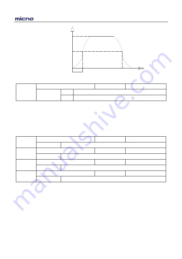
Rated frequency (fb)
Output frequency (Hz)
Setting frequency (f)
Time (t)
Figure 6-11 S-curve ACC/DEC A diagram
P6-10
Stop mode
Factory default
0
Setting range
0
Deceleration to stop
1
Coast to stop
0: Deceleration to stop
After the stop command is valid, the inverter reduces the output frequency according to the DEC time and
will stop after the frequency reduces to zero.
1: Coast to stop
After the stop command is valid, the inverter blocks the output immediately. The motor coasts to stop
according to the mechanical inertia.
P6-11
DC braking start frequency after stop
Factory default
0.00Hz
Setting range
0.00Hz ~ P0.10 (maximum frequency)
P6-12
DC braking waiting time after stop
Factory default
0.0s
Setting range
0.0s ~ 100.0s
P6-13
DC braking current after stop
Factory default
0%
Setting range
0% ~ 100%
P6-14
DC braking time after stop
Factory default
0.0s
Setting range
0.0s ~ 100.0s
DC braking start frequency after stop: Start the DC braking when running frequency reaches this frequency
determined by P6-11.
DC braking waiting time after stop: Inverter blocks the output before starting the DC braking. After this
waiting time, the DC braking will be started so as to prevent over-current fault caused by DC braking at
high speed.
DC brake current after stop: The value of P6-13 is the percentage of rated current of inverter. The bigger
the DC braking current is, the greater the braking torque is.
DC brake time after stop: The time which is used to perform DC braking. If the time is 0, the DC braking will
be invalid.


