


7A-26
ENGINE ATTACHMENTS
90-13645--2
495
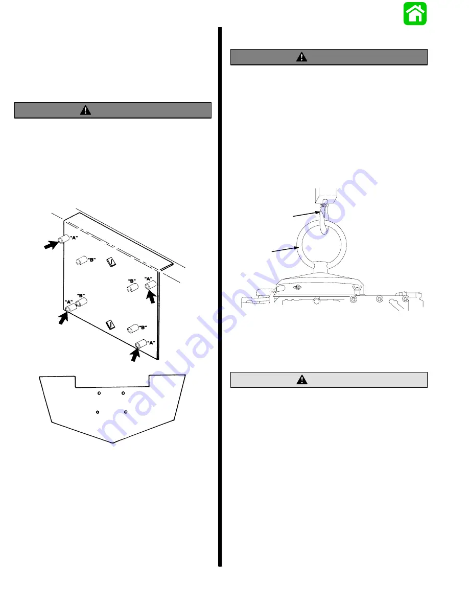
Drilling Outboard Mounting Holes
IMPORTANT: Before drilling any mounting holes,
carefully read “Determining Recommended Out-
board Motor Mounting Height”, preceding. There
is a 3/4 in. (19mm) difference between outboard
mounting holes in transom bracket.
WARNING
DO NOT, under any circumstances, allow upper
outboard mounting bolts to be closer than 1 in.
(25.4mm) from top of boat transom. Upper
mounting bolts must never be installed thru
shims.
IMPORTANT: If using “Transom Drill Fixture”
(91-98234A2), use drill guide holes marked “A”
when drilling outboard mounting holes.
Lifting Engine
WARNING
Make sure that lifting eye is threaded into flywheel
a minimum of 5 turns and that hoist has a
minimum lift capacity of at least 500 lbs. (227 kg)
BEFORE lifting engine.
1. Remove cowling from engine and plastic cap from
center of flywheel. Thread lifting eye into flywheel
hub a minimum of 5 turns. Replace plastic cap af-
ter installation.
2. Connect hoist [minimum lift capacity of 500 lbs.
(227 kg)] to lifting eye. Lift engine and place on
boat transom.
25929
a
b
a - Lifting Eye (C-91-75132)
b - Hoist
Installing Engine to Transom
Marine sealer must be used on shanks of
mounting bolts to make a water-tight installation.
CAUTION
NOTE: Because of clearance on some boats it will be
necessary to install steering cable on engine before
installing engine to transom. Refer to page 1 of this
instruction.
IMPORTANT: DO NOT use an impact driver when
tightening transom mounting bolts.
1. Determine engine mounting height dimension
from graph (STEP 1) and use engine mounting
holes that will position engine nearest to recom-
mended height.
Содержание 100
Страница 4: ...GENERAL INFORMATION AND SPECIFICATIONS 1 ...
Страница 18: ...IGNITION SYSTEM ELECTRICAL AND IGNITION A 2 ...
Страница 30: ...11669 BATTERY CHARGING SYSTEM AND STARTING SYSTEM ELECTRICAL AND IGNITION B 2 ...
Страница 58: ...22480 TIMING SYNCHRONIZING ADJUSTING ELECTRICAL AND IGNITION C 2 ...
Страница 71: ...WIRING DIAGRAMS ELECTRICAL AND IGNITION D 2 ...
Страница 86: ...FUEL SYSTEM AND CARBURETION A 3 ...
Страница 118: ...OIL INJECTION SYSTEM B 3 ...
Страница 127: ...20032 3 CYLINDER ENGINES POWERHEAD A 4 ...
Страница 168: ...791 H GEAR HOUSING LOWER UNIT A 5 ...
Страница 170: ...5A 1 90 13645 2 1095 LOWER UNIT Notes ...
Страница 205: ...MID SECTION LOWER UNIT B 5 ...
Страница 207: ...5B 1 90 13645 2 495 LOWER UNIT Notes ...
Страница 218: ...SHOCK ABSORBER LOWER UNIT C 5 ...
Страница 223: ...17250 DESIGN I SIDE FILL RESERVOIR POWER TRIM A 6 ...
Страница 233: ...6A 9 POWER TRIM 90 13645 2 495 Commander Side Mount Remote Control Wiring Diagram ...
Страница 268: ...DESIGN II AFT FILL RESERVOIR POWER TRIM B 6 51344 ...
Страница 305: ...SINGLE RAM POWER TRIM C 6 51485 ...
Страница 309: ...6C 3 90 13645 2 495 POWER TRIM Notes ...
Страница 340: ...50099 ENGINE ATTACHMENTS ENGINE INSTALLATION 7 A ...
Страница 369: ...TILLER HANDLE AND CO PILOT OUTBOARD MOTOR INSTALLATION ATTACHMENTS 7 B ...
Страница 371: ...7B 1 90 13645 2 495 OUTBOARD MOTOR INSTALLATION ATTACHMENTS Notes ...