


6B-16
90-13645--2
495
POWER TRIM
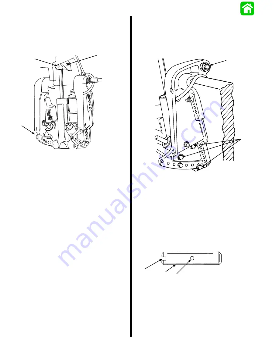
IMPORTANT: Cross pin (a) should not be reused.
Replace with new cross pin.
7. Drive out cross pin, push out upper swivel pin, and
remove 3 screws and washers retaining trim sys-
tem. Remove system from outboard.
51339
a
b
c
a - Cross Pin
b - Upper Swivel Pin
c - Port Transom Bracket Screws and Washers (3) - Remove to
release trim system from outboard.
Installation
1. Paint any exposed metal surfaces to prevent
corrosion.
2. Apply Loctite 271 to screws. Install trim system,
starboard transom bracket, and tilt tube nut.
51375
a
b
c
a - Screw (6) - Torque to 45 lb. ft. (61.0 N·m)
b - Flatwasher (6) - Install one per screw
c - Tilt Tube Nut
3. Use a 12 volt power source to extend tilt ram up
to align upper swivel shaft hole and end of ram.
Connect trim motor wires (BLUE wire to positive
(+), BLACK wire to negative (-). If ram extends too
far, retract ram by connecting GREEN wire to pos-
itive (+).
4. Install Upper Swivel Pin with slotted end to left
(port) side of engine.
a
b
c
a - Upper Swivel Pin
b - Slotted End
c - Cross Hole (in line with slotted end)
IMPORTANT: Cross pin should not be reused. In-
stall a new pin.
Содержание 100
Страница 4: ...GENERAL INFORMATION AND SPECIFICATIONS 1 ...
Страница 18: ...IGNITION SYSTEM ELECTRICAL AND IGNITION A 2 ...
Страница 30: ...11669 BATTERY CHARGING SYSTEM AND STARTING SYSTEM ELECTRICAL AND IGNITION B 2 ...
Страница 58: ...22480 TIMING SYNCHRONIZING ADJUSTING ELECTRICAL AND IGNITION C 2 ...
Страница 71: ...WIRING DIAGRAMS ELECTRICAL AND IGNITION D 2 ...
Страница 86: ...FUEL SYSTEM AND CARBURETION A 3 ...
Страница 118: ...OIL INJECTION SYSTEM B 3 ...
Страница 127: ...20032 3 CYLINDER ENGINES POWERHEAD A 4 ...
Страница 168: ...791 H GEAR HOUSING LOWER UNIT A 5 ...
Страница 170: ...5A 1 90 13645 2 1095 LOWER UNIT Notes ...
Страница 205: ...MID SECTION LOWER UNIT B 5 ...
Страница 207: ...5B 1 90 13645 2 495 LOWER UNIT Notes ...
Страница 218: ...SHOCK ABSORBER LOWER UNIT C 5 ...
Страница 223: ...17250 DESIGN I SIDE FILL RESERVOIR POWER TRIM A 6 ...
Страница 233: ...6A 9 POWER TRIM 90 13645 2 495 Commander Side Mount Remote Control Wiring Diagram ...
Страница 268: ...DESIGN II AFT FILL RESERVOIR POWER TRIM B 6 51344 ...
Страница 305: ...SINGLE RAM POWER TRIM C 6 51485 ...
Страница 309: ...6C 3 90 13645 2 495 POWER TRIM Notes ...
Страница 340: ...50099 ENGINE ATTACHMENTS ENGINE INSTALLATION 7 A ...
Страница 369: ...TILLER HANDLE AND CO PILOT OUTBOARD MOTOR INSTALLATION ATTACHMENTS 7 B ...
Страница 371: ...7B 1 90 13645 2 495 OUTBOARD MOTOR INSTALLATION ATTACHMENTS Notes ...