


6A-38 POWER TRIM 90-13645--2
495
Trim Sender (Optional Accessory) Test
Check trim sender BLACK lead for proper ground.
Trim engine to full “Down” position.
Place ignition switch in “Off” position.
Connect Ohmmeter (R x 1 scale) leads between
engine ground and Point 1.
Depress “Up” trim button. Ohmmeter needle should
move as the engine is trimmed up. If needle does not
move, the trim sender is defective.
a
b
c
BRN/WHT
BLK
BRN/WHT
1
a - Trim Sender
b - Connect with Screw and Hex Nut (Coat with Liquid
Neoprene)
c - Rubber Sleeve (Slide Over Connection)
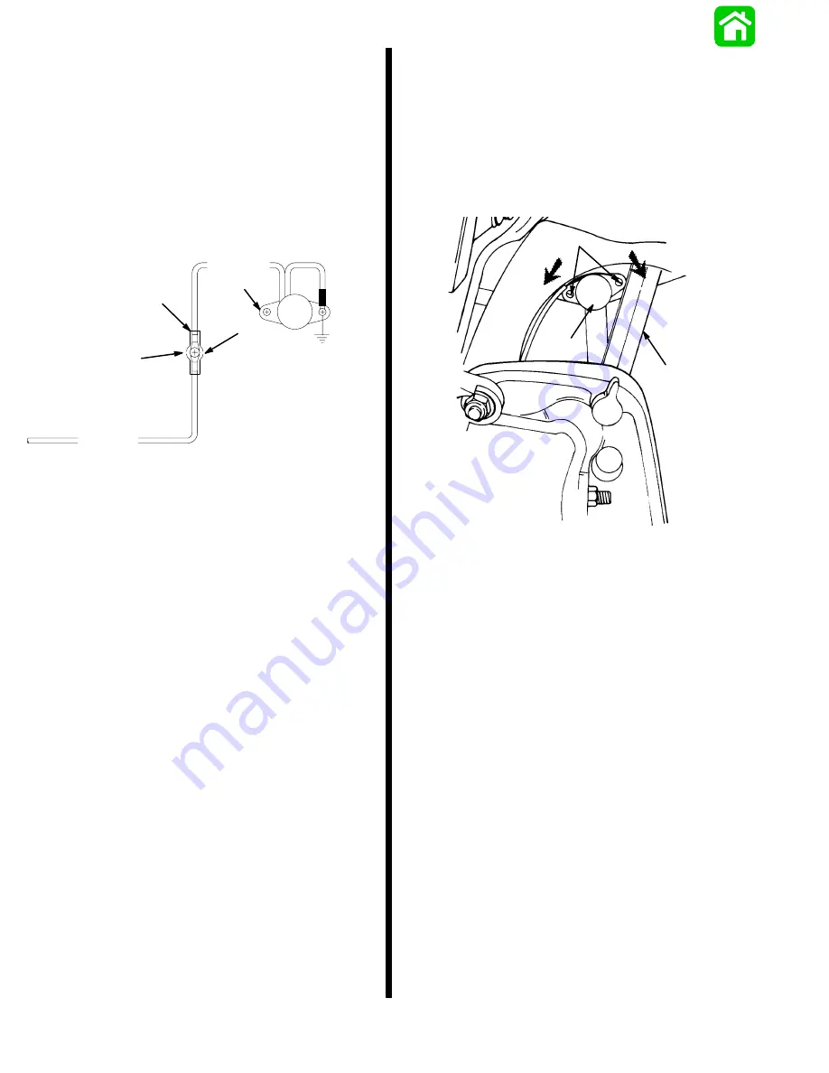
Trim Indicator Gauge (Optional
Accessory) Needle Adjustment
Trim engine to full “Down” position. If trim indicator
needle is not at the bottom of the green arc on the
gauge face, tilt engine “up” to gain access to the trim
sender. Loosen screws and reposition trim sender, as
shown. Trim engine to full “Down” position and re-
check needle position.
22744
a
b
c
d
e
a - Trim Sender
b - Screws, Loosen to Rotate Sender
c - Turn Sender Counterclockwise to Raise Needle Reading
d - Turn Sender Clockwise to Lower Needle Reading
e - Tilt Lock Lever
Motor Repair
REMOVAL
NOTE: Power Trim assembly does not have to be re-
moved from engine to repair motor.
Remove motor and pump as an assembly; refer to
“Pump Replacement,” preceding.
DISASSEMBLY
Refer to “Pump Replacement,” preceding, for proper
disassembly procedure.
CLEANING AND INSPECTION
Inspect O-rings, and replace if damaged.
Clean, inspect and test motor components; refer to
“Brush Replacement,” “Armature Test,” and “Field
Tests,” preceding.
Содержание 100
Страница 4: ...GENERAL INFORMATION AND SPECIFICATIONS 1 ...
Страница 18: ...IGNITION SYSTEM ELECTRICAL AND IGNITION A 2 ...
Страница 30: ...11669 BATTERY CHARGING SYSTEM AND STARTING SYSTEM ELECTRICAL AND IGNITION B 2 ...
Страница 58: ...22480 TIMING SYNCHRONIZING ADJUSTING ELECTRICAL AND IGNITION C 2 ...
Страница 71: ...WIRING DIAGRAMS ELECTRICAL AND IGNITION D 2 ...
Страница 86: ...FUEL SYSTEM AND CARBURETION A 3 ...
Страница 118: ...OIL INJECTION SYSTEM B 3 ...
Страница 127: ...20032 3 CYLINDER ENGINES POWERHEAD A 4 ...
Страница 168: ...791 H GEAR HOUSING LOWER UNIT A 5 ...
Страница 170: ...5A 1 90 13645 2 1095 LOWER UNIT Notes ...
Страница 205: ...MID SECTION LOWER UNIT B 5 ...
Страница 207: ...5B 1 90 13645 2 495 LOWER UNIT Notes ...
Страница 218: ...SHOCK ABSORBER LOWER UNIT C 5 ...
Страница 223: ...17250 DESIGN I SIDE FILL RESERVOIR POWER TRIM A 6 ...
Страница 233: ...6A 9 POWER TRIM 90 13645 2 495 Commander Side Mount Remote Control Wiring Diagram ...
Страница 268: ...DESIGN II AFT FILL RESERVOIR POWER TRIM B 6 51344 ...
Страница 305: ...SINGLE RAM POWER TRIM C 6 51485 ...
Страница 309: ...6C 3 90 13645 2 495 POWER TRIM Notes ...
Страница 340: ...50099 ENGINE ATTACHMENTS ENGINE INSTALLATION 7 A ...
Страница 369: ...TILLER HANDLE AND CO PILOT OUTBOARD MOTOR INSTALLATION ATTACHMENTS 7 B ...
Страница 371: ...7B 1 90 13645 2 495 OUTBOARD MOTOR INSTALLATION ATTACHMENTS Notes ...