


90-13645--2
495
6B-19
POWER TRIM
11. Run trim “UP”. The minimum pressure should be
1300 P.S.I. (91 kg/cm
2
).
12. Run trim “DOWN” to release pressure and re-
move spare tilt pin or bolts and nuts.
13. Tilt outboard full “UP” and engage tilt lock lever.
14. Slowly remove “Fill” plug to bleed pressure.
15. Open Manual Release Valve 3 to 4 turns to bleed
any remaining pressure.
16. Remove test gauge hose and adapter, and install
allen plug.
NOTE: If pressure is less than 1300 PSI (91 kg/cm2),
troubleshoot system per instructions on page 6B-7.
“DOWN” Pressure Check
1. Repeat steps 1 through 4 from preceding “UP”
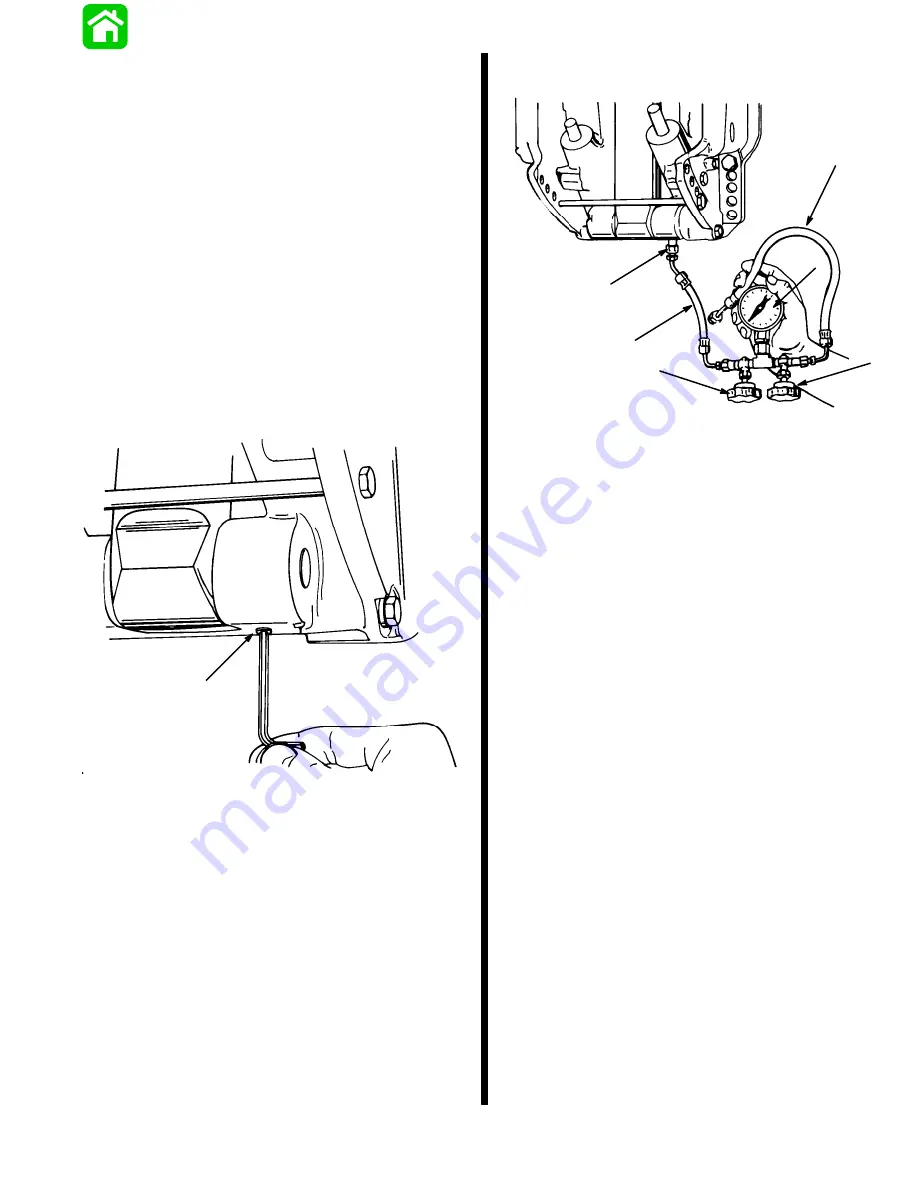
pressure check, removing allen plug as shown.
51367
a
a - Allen Plug
2. Install components.
51360
a
b
c
d
e
f
a - Adapter Fitting (22-11243)
b - Hose (route hose so it will not be pinched when outboard is
trimmed “DOWN”)
c - Test Gauge Assembly
d - Valve
e - Valve
f - Hose (not used for this test)
3. Open valve (d) and close valve (e).
4. Install fill plug.
5. Close Manual Release Valve (clockwise).
6. Run trim “DOWN”. Minimum pressure should be
500 P.S.I. (35 kg/cm
2
).
7. Tilt outboard full “UP” and engage tilt lock lever.
8. Slowly remove “Fill” plug to bleed pressure.
9. Open Manual Release Valve 3 to 4 turns to re-
lease any remaining pressure.
10. Remove test gauge hose and adapter fitting. In-
stall allen plug.
11. Fill Power Trim system and purge system; refer to
“Fill, Check, and Purge” preceding.
NOTE: If pressure is less than 500 PSI (35 kg/cm
2
),
troubleshoot system per instructions on page 6B-7.
Содержание 100
Страница 4: ...GENERAL INFORMATION AND SPECIFICATIONS 1 ...
Страница 18: ...IGNITION SYSTEM ELECTRICAL AND IGNITION A 2 ...
Страница 30: ...11669 BATTERY CHARGING SYSTEM AND STARTING SYSTEM ELECTRICAL AND IGNITION B 2 ...
Страница 58: ...22480 TIMING SYNCHRONIZING ADJUSTING ELECTRICAL AND IGNITION C 2 ...
Страница 71: ...WIRING DIAGRAMS ELECTRICAL AND IGNITION D 2 ...
Страница 86: ...FUEL SYSTEM AND CARBURETION A 3 ...
Страница 118: ...OIL INJECTION SYSTEM B 3 ...
Страница 127: ...20032 3 CYLINDER ENGINES POWERHEAD A 4 ...
Страница 168: ...791 H GEAR HOUSING LOWER UNIT A 5 ...
Страница 170: ...5A 1 90 13645 2 1095 LOWER UNIT Notes ...
Страница 205: ...MID SECTION LOWER UNIT B 5 ...
Страница 207: ...5B 1 90 13645 2 495 LOWER UNIT Notes ...
Страница 218: ...SHOCK ABSORBER LOWER UNIT C 5 ...
Страница 223: ...17250 DESIGN I SIDE FILL RESERVOIR POWER TRIM A 6 ...
Страница 233: ...6A 9 POWER TRIM 90 13645 2 495 Commander Side Mount Remote Control Wiring Diagram ...
Страница 268: ...DESIGN II AFT FILL RESERVOIR POWER TRIM B 6 51344 ...
Страница 305: ...SINGLE RAM POWER TRIM C 6 51485 ...
Страница 309: ...6C 3 90 13645 2 495 POWER TRIM Notes ...
Страница 340: ...50099 ENGINE ATTACHMENTS ENGINE INSTALLATION 7 A ...
Страница 369: ...TILLER HANDLE AND CO PILOT OUTBOARD MOTOR INSTALLATION ATTACHMENTS 7 B ...
Страница 371: ...7B 1 90 13645 2 495 OUTBOARD MOTOR INSTALLATION ATTACHMENTS Notes ...