


7A-11
ENGINE ATTACHMENTS
90-13645--2
495
a
b
c
d
e
f
g
d
b
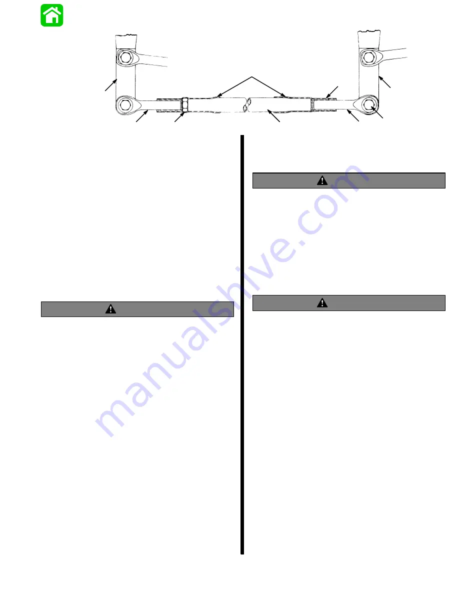
a - Jam Nut; Torque to 20 lbs. ft. (27.1 N
m)
b - Engine Steering Arm
c - Coupler
d - Steering Eye
e - Rubber Sleeves
f - Rubber Bushing
g - Pivot Bolt and Locknut; Torque to 20 lbs. ft. (27.1 N
m)
Figure 9. Coupler Parts Sequence
4. Thread steering eyes (Figures 8 and 9) into cou-
pler and adjust steering eyes so that distance be-
tween centers of pivot holes in steering eyes is the
same distance as between centers of threaded
pivot holes in engine steering arms. Exposed
steering eye threads should be equal at both ends
of coupler and must not extend out of coupler
more than 2-3/4
″
(70mm).
WARNING
Both steering eyes must be threaded into coupler
3/4
″
(19mm) minimum. Thread length of steering
eye is 3-1/2
″
(89mm), so exposed thread must not
extend out of coupler more than 2-3/4
″
(69.8mm).
Failure to adhere to this requirement could result
in steering system failure.
5. Lubricate steering eye threads, pivot bolts and
ball joints with Quicksilver Corrosion Grease
(92-78376-12) or Corrosion Guard (92-78379-12)
before assembling.
6. Assemble steering eyes and coupler to top side
front holes of steering arm with pivot bolts and
locknuts, as shown in Figures 6 and 9.
IMPORTANT: With steering eyes and coupler
installed and before tightening pivot bolts, check
engine alignment. Distance between pivot bolts’
centers and distance between propeller shaft
centers must be equal for proper steering. If ad-
justment is necessary, remove pivot bolt from one
steering eye and turn eye in or out to correct align-
ment. Both steering eyes MUST BE threaded into
coupler 3/4
″
(19mm) minimum.
7. Torque pivot bolts to 20 lbs. ft. (27.1 N
m), then
thread self-locking nut onto bolts and torque nuts
to 20 lbs. ft. (27.1 N
m).
WARNING
Both steering eyes MUST BE threaded into coupler
3/4
″
minimum, and jam nut (Figures 8 and 9) must
be secured against coupler to prevent coupler from
turning. Torque jam nut to 20 lbs. ft. (13.5 N·m).
8. Secure coupler with jam nut, as shown in Figure 9.
Torque to 20 lbs. ft. (27.1 N
m).
9. Position rubber bushings as shown above.
10. Slide both rubber sleeves over exposed threads
on each steering eye (Figure 9).
WARNING
Tension adjustment – steering cable mounting
tube must be adjusted away from end of steering
cable when adding tension to steering system (to
remove slack). Failure to adjust tube this way may
result in hard steering, if one engine is tilted up
while operating boat.
Steering System Tension Adjustment
OPPOSITE SIDE ROUTED STEERING CABLES
IMPORTANT: After this Ride-Guide Attachment
Kit is installed, there must be proper tension in the
steering system. Not enough tension will cause
slack (play) in steering system. Too much tension
will cause steering cables to bind. Perform Step
1, following, to adjust for correct tension.
1. Loosen adjustment nuts and pull steering cable
mounting tube (by hand) away from end of steer-
ing cable (to remove slack in steering system).
Tighten adjustment nuts and check system for
slack (play) or too much tightness. If steering sys-
tem is too tight, readjust tube toward end of steer-
ing cable (Figure 10) or, if too much slack (play)
exists in system, readjust tube away from end of
steering cable (Figure 10). Tighten nuts and read-
just, if necessary.
Содержание 100
Страница 4: ...GENERAL INFORMATION AND SPECIFICATIONS 1 ...
Страница 18: ...IGNITION SYSTEM ELECTRICAL AND IGNITION A 2 ...
Страница 30: ...11669 BATTERY CHARGING SYSTEM AND STARTING SYSTEM ELECTRICAL AND IGNITION B 2 ...
Страница 58: ...22480 TIMING SYNCHRONIZING ADJUSTING ELECTRICAL AND IGNITION C 2 ...
Страница 71: ...WIRING DIAGRAMS ELECTRICAL AND IGNITION D 2 ...
Страница 86: ...FUEL SYSTEM AND CARBURETION A 3 ...
Страница 118: ...OIL INJECTION SYSTEM B 3 ...
Страница 127: ...20032 3 CYLINDER ENGINES POWERHEAD A 4 ...
Страница 168: ...791 H GEAR HOUSING LOWER UNIT A 5 ...
Страница 170: ...5A 1 90 13645 2 1095 LOWER UNIT Notes ...
Страница 205: ...MID SECTION LOWER UNIT B 5 ...
Страница 207: ...5B 1 90 13645 2 495 LOWER UNIT Notes ...
Страница 218: ...SHOCK ABSORBER LOWER UNIT C 5 ...
Страница 223: ...17250 DESIGN I SIDE FILL RESERVOIR POWER TRIM A 6 ...
Страница 233: ...6A 9 POWER TRIM 90 13645 2 495 Commander Side Mount Remote Control Wiring Diagram ...
Страница 268: ...DESIGN II AFT FILL RESERVOIR POWER TRIM B 6 51344 ...
Страница 305: ...SINGLE RAM POWER TRIM C 6 51485 ...
Страница 309: ...6C 3 90 13645 2 495 POWER TRIM Notes ...
Страница 340: ...50099 ENGINE ATTACHMENTS ENGINE INSTALLATION 7 A ...
Страница 369: ...TILLER HANDLE AND CO PILOT OUTBOARD MOTOR INSTALLATION ATTACHMENTS 7 B ...
Страница 371: ...7B 1 90 13645 2 495 OUTBOARD MOTOR INSTALLATION ATTACHMENTS Notes ...