


6B-6
90-13645--2
495
POWER TRIM
Striker Plate Replacement
Visually inspect striker plates (a) and replace if worn
excessively.
27930
a
b
c
a - Striker Plate (2)
b - Lockwasher
c - Locknut - Torque to 80 lb. in. (9.0 N·m)
Anode Plate
Anode plate (a) is a self-sacrificing alloy plate that is
consumed gradually by corrosion while providing pro-
tection to the midsection and power trim from galvanic
corrosion. Replace anode plate when it is 50% con-
sumed.
27932
a
a - Anode Plate
IMPORTANT: Do not paint or place protective
coating on anode plate, or corrosion protection
function will be lost.
Trim Indicator Gauge
A Quicksilver Trim Indicator Gauge accessory kit is
available for the power trim sender (if not previously
installed).
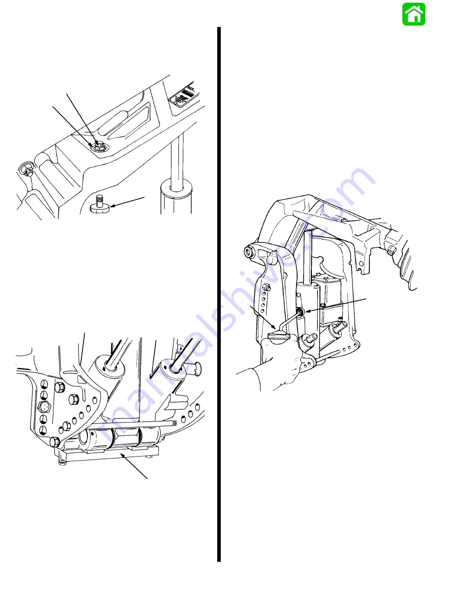
Fill, Check, and Purge - Power Trim
System
IMPORTANT: This trim system is pressurized. Re-
move “Fill” plug only when outboard is tilted to
the full “Up” position or the trim/tilt rams are fully
extended. Retighten “Fill” plug before tilting out-
board down or retracting tilt/trim rams.
Remove “Fill” plug and O-ring. System is full
when oil level is present at fill hole. Tighten “Fill”
plug securely.
51344
a
b
a - Fill Plug and O-ring (remove to fill system, tighten securely)
b - Oil Can (fill system with Quicksilver Power Trim and Steering
Fluid)
NOTE: Automatic Transmission Fluid (ATF) Type F,
FA, or Dexron II may be used.
Содержание 100
Страница 4: ...GENERAL INFORMATION AND SPECIFICATIONS 1 ...
Страница 18: ...IGNITION SYSTEM ELECTRICAL AND IGNITION A 2 ...
Страница 30: ...11669 BATTERY CHARGING SYSTEM AND STARTING SYSTEM ELECTRICAL AND IGNITION B 2 ...
Страница 58: ...22480 TIMING SYNCHRONIZING ADJUSTING ELECTRICAL AND IGNITION C 2 ...
Страница 71: ...WIRING DIAGRAMS ELECTRICAL AND IGNITION D 2 ...
Страница 86: ...FUEL SYSTEM AND CARBURETION A 3 ...
Страница 118: ...OIL INJECTION SYSTEM B 3 ...
Страница 127: ...20032 3 CYLINDER ENGINES POWERHEAD A 4 ...
Страница 168: ...791 H GEAR HOUSING LOWER UNIT A 5 ...
Страница 170: ...5A 1 90 13645 2 1095 LOWER UNIT Notes ...
Страница 205: ...MID SECTION LOWER UNIT B 5 ...
Страница 207: ...5B 1 90 13645 2 495 LOWER UNIT Notes ...
Страница 218: ...SHOCK ABSORBER LOWER UNIT C 5 ...
Страница 223: ...17250 DESIGN I SIDE FILL RESERVOIR POWER TRIM A 6 ...
Страница 233: ...6A 9 POWER TRIM 90 13645 2 495 Commander Side Mount Remote Control Wiring Diagram ...
Страница 268: ...DESIGN II AFT FILL RESERVOIR POWER TRIM B 6 51344 ...
Страница 305: ...SINGLE RAM POWER TRIM C 6 51485 ...
Страница 309: ...6C 3 90 13645 2 495 POWER TRIM Notes ...
Страница 340: ...50099 ENGINE ATTACHMENTS ENGINE INSTALLATION 7 A ...
Страница 369: ...TILLER HANDLE AND CO PILOT OUTBOARD MOTOR INSTALLATION ATTACHMENTS 7 B ...
Страница 371: ...7B 1 90 13645 2 495 OUTBOARD MOTOR INSTALLATION ATTACHMENTS Notes ...