


7A-8
ENGINE ATTACHMENTS
90-13645--2
495
Opposite Side Routed
Steering Cables and
Attaching Kit Installation
(ONE CABLE ROUTED DOWN STARBOARD SIDE
OF BOAT AND ONE CABLE ROUTED DOWN
PORT SIDE OF BOAT)
IMPORTANT: Steering cable must be installed into
tilt tube of “port” engine before engine is
mounted.
Super Ride-Guide Steering
Kit Installation
Install Super Ride-Guide Steering Kit in accordance
with instructions included with Super Ride-Guide Kit.
Installing Steering Cables and
Steering Link Rods to Engines
1. Install tube mounting bracket to (starboard)
mounted engine with 2 locking retainers and 4
bolts. Torque bolts to 100 lbs. in. (11.3 N
m) and
bend end of locking retainers up against flat on
each bolt, as shown in Figure 1.
WARNING
Locking retainer ends must be bent up and
against flat on each bolt, that secures tube
mounting bracket to engine, to prevent bolts from
turning out.
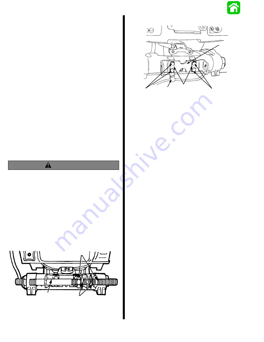
2. Install steering cable mounting tube into mounting
bracket with 2 adjustment nuts and tab lockwash-
ers, as shown in Figure 2. Be sure that longer
threaded end of tube is toward steering cable at-
taching nut side of engine.
3. Temporarily adjust tube so that longer, threaded
end of tube is aligned with outward edge of tran-
som bracket. DO NOT tighten adjustment nuts at
this time.
a
b
c
50130
a - Tube Mounting Bracket
b - Bolts
c - Locking Retainers (Bend Ends Up and Against
Flat on Bolts.)
Figure 1. Tube Mounting Bracket Installed
51891
a
c
b
d
d
a - Mounting Bracket for Steering Cable Mounting Tube
b - “J” Clip - Supplied with Outboard
c - Locking Retainers (2)
d - Bolts (4) - 5/8 in. (16mm) Long - Torque to 100 lb. in.
(11.3 N
m), then Bend Corner Tabs of Locking Retainers Up
and Against Flats on Each Bolt
Figure 2. Steering Cable Mounting Tube Installed
4. Install steering cables, as follows:
IMPORTANT: Lubricate inside of (port mounted)
engine tilt tube and inside of steering cable
mounting tube with Quicksilver 2-4-C w/Teflon.
Make sure that rubber O-ring seal (located in en-
gine tilt tube) is lubricated.
a. Lubricate inside of (port) engine tilt tube with
Quicksilver 2-4-C w/Teflon. Make sure that rub-
ber O-ring seal (located in engine tilt tube) is lu-
bricated.
b. Lubricate inside of steering cable mounting
tube with Quicksilver 2-4-C w/Teflon.
Содержание 100
Страница 4: ...GENERAL INFORMATION AND SPECIFICATIONS 1 ...
Страница 18: ...IGNITION SYSTEM ELECTRICAL AND IGNITION A 2 ...
Страница 30: ...11669 BATTERY CHARGING SYSTEM AND STARTING SYSTEM ELECTRICAL AND IGNITION B 2 ...
Страница 58: ...22480 TIMING SYNCHRONIZING ADJUSTING ELECTRICAL AND IGNITION C 2 ...
Страница 71: ...WIRING DIAGRAMS ELECTRICAL AND IGNITION D 2 ...
Страница 86: ...FUEL SYSTEM AND CARBURETION A 3 ...
Страница 118: ...OIL INJECTION SYSTEM B 3 ...
Страница 127: ...20032 3 CYLINDER ENGINES POWERHEAD A 4 ...
Страница 168: ...791 H GEAR HOUSING LOWER UNIT A 5 ...
Страница 170: ...5A 1 90 13645 2 1095 LOWER UNIT Notes ...
Страница 205: ...MID SECTION LOWER UNIT B 5 ...
Страница 207: ...5B 1 90 13645 2 495 LOWER UNIT Notes ...
Страница 218: ...SHOCK ABSORBER LOWER UNIT C 5 ...
Страница 223: ...17250 DESIGN I SIDE FILL RESERVOIR POWER TRIM A 6 ...
Страница 233: ...6A 9 POWER TRIM 90 13645 2 495 Commander Side Mount Remote Control Wiring Diagram ...
Страница 268: ...DESIGN II AFT FILL RESERVOIR POWER TRIM B 6 51344 ...
Страница 305: ...SINGLE RAM POWER TRIM C 6 51485 ...
Страница 309: ...6C 3 90 13645 2 495 POWER TRIM Notes ...
Страница 340: ...50099 ENGINE ATTACHMENTS ENGINE INSTALLATION 7 A ...
Страница 369: ...TILLER HANDLE AND CO PILOT OUTBOARD MOTOR INSTALLATION ATTACHMENTS 7 B ...
Страница 371: ...7B 1 90 13645 2 495 OUTBOARD MOTOR INSTALLATION ATTACHMENTS Notes ...