


4A-23
90-13645--2
495
POWERHEAD
Connecting Rods
If necessary, clean connecting rod surfaces as fol-
lows:
S
Attach end caps to connecting rods. Following
these directions, tighten rod cap attaching bolts to
specifications. Recheck alignment. Refer to
4A-32.
Crocus cloth MUST BE USED to clean bearing
surface at crankshaft end of connecting rod. DO
NOT use any other type of abrasive cloth.
CAUTION
S
Clean crankshaft end of connecting rod by using
crocus cloth placed in a slotted 3/8 in. (9.5mm) di-
ameter shaft, as shown. Insert shaft in a drill press
and operate press at full speed while keeping con-
necting rod at a 90
_
angle to slotted shaft.
IMPORTANT: Clean connecting rod just enough to
clean bearing surfaces. DO NOT continue to clean
after marks are removed from bearing surfaces.
S
Clean piston pin end of connecting rod, using
same method as above. Use 320 grit carborun-
dum cloth instead of crocus cloth.
S
Thoroughly wash connecting rods to remove abra-
sive grit. Recheck bearing surfaces of connecting
rods. Replace any connecting rod that cannot be
properly polished. Lubricate bearing surfaces of
connecting rods which will be reused with 2 cycle
engine oil to prevent rust.
51083
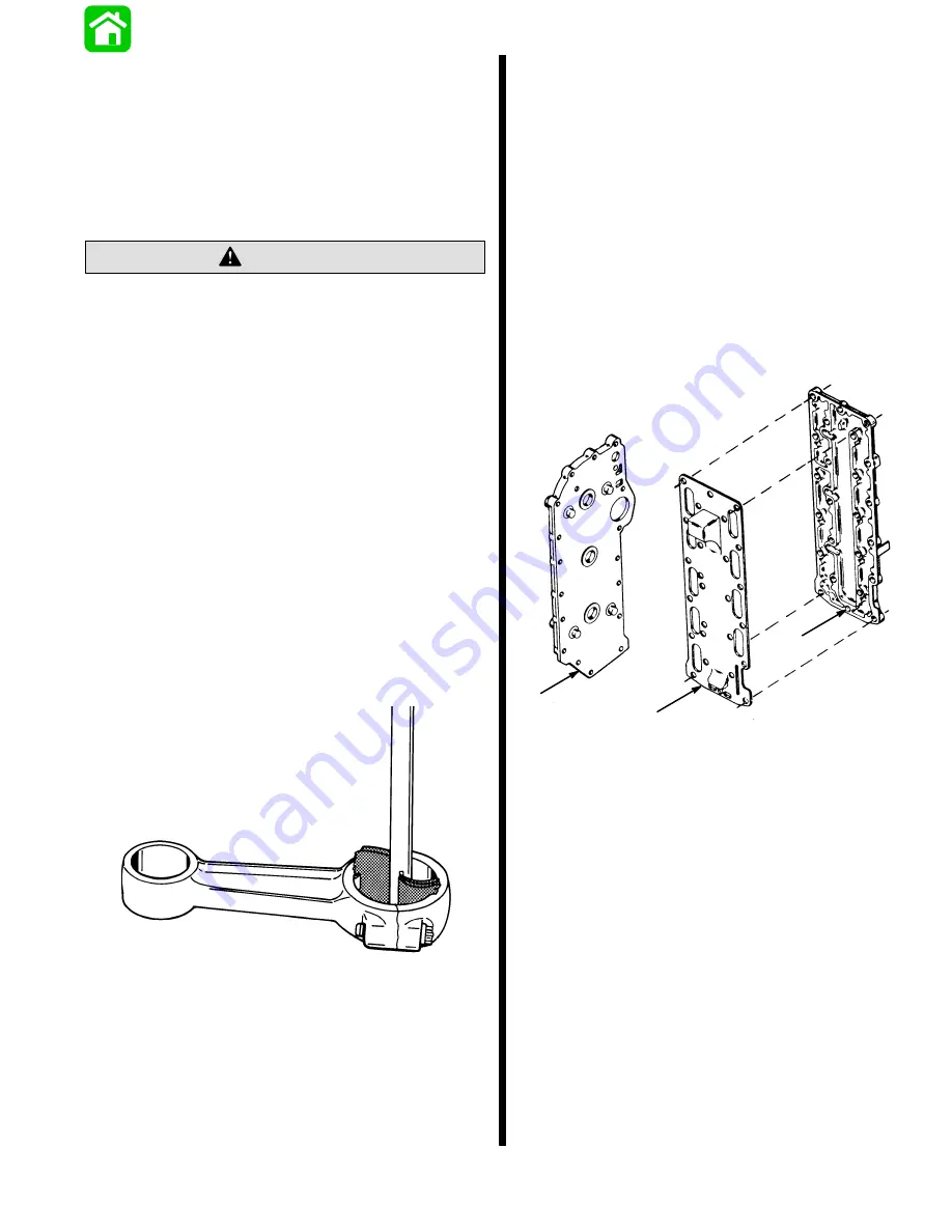
Cylinder Cover, Exhaust Divider Plate
and Exhaust Cover
S
Thoroughly clean cylinder cover and gasket
surfaces.
S
Inspect cylinder cover. Check for cracks which
could cause water leakage.
S
Replace cylinder cover as necessary.
S
Thoroughly clean gasket surfaces of exhaust di-
vider plate and exhaust manifold cover.
S
Inspect exhaust divider plate and exhaust
manifold cover for grooves, cracks or distortion
that could cause leakage. Replace parts as
necessary.
a
b
c
a - Cylinder Cover
b - Divider Plate
c - Exhaust Cover
Содержание 100
Страница 4: ...GENERAL INFORMATION AND SPECIFICATIONS 1 ...
Страница 18: ...IGNITION SYSTEM ELECTRICAL AND IGNITION A 2 ...
Страница 30: ...11669 BATTERY CHARGING SYSTEM AND STARTING SYSTEM ELECTRICAL AND IGNITION B 2 ...
Страница 58: ...22480 TIMING SYNCHRONIZING ADJUSTING ELECTRICAL AND IGNITION C 2 ...
Страница 71: ...WIRING DIAGRAMS ELECTRICAL AND IGNITION D 2 ...
Страница 86: ...FUEL SYSTEM AND CARBURETION A 3 ...
Страница 118: ...OIL INJECTION SYSTEM B 3 ...
Страница 127: ...20032 3 CYLINDER ENGINES POWERHEAD A 4 ...
Страница 168: ...791 H GEAR HOUSING LOWER UNIT A 5 ...
Страница 170: ...5A 1 90 13645 2 1095 LOWER UNIT Notes ...
Страница 205: ...MID SECTION LOWER UNIT B 5 ...
Страница 207: ...5B 1 90 13645 2 495 LOWER UNIT Notes ...
Страница 218: ...SHOCK ABSORBER LOWER UNIT C 5 ...
Страница 223: ...17250 DESIGN I SIDE FILL RESERVOIR POWER TRIM A 6 ...
Страница 233: ...6A 9 POWER TRIM 90 13645 2 495 Commander Side Mount Remote Control Wiring Diagram ...
Страница 268: ...DESIGN II AFT FILL RESERVOIR POWER TRIM B 6 51344 ...
Страница 305: ...SINGLE RAM POWER TRIM C 6 51485 ...
Страница 309: ...6C 3 90 13645 2 495 POWER TRIM Notes ...
Страница 340: ...50099 ENGINE ATTACHMENTS ENGINE INSTALLATION 7 A ...
Страница 369: ...TILLER HANDLE AND CO PILOT OUTBOARD MOTOR INSTALLATION ATTACHMENTS 7 B ...
Страница 371: ...7B 1 90 13645 2 495 OUTBOARD MOTOR INSTALLATION ATTACHMENTS Notes ...