


7A-1
ENGINE ATTACHMENTS
90-13645--2
495
Steering Cable and Steering
Link Rod Installation
Control cables must be the correct length when
installed. Cables that are too long may bind or
kink putting extra stress on cables.
CAUTION
1. Install steering mount and steering wheel in
accordance with installation instructions that
accompany each.
2. Lubricate seal inside of engine tilt tube and entire
steering cable end with Quicksilver 2-4-C
w/Teflon.
51890
a
a - Seal
IMPORTANT: Before installing steering cable into
tilt tube, lubricate seal and entire cable end with
Quicksilver 2-4-C w/Teflon.
3. Insert steering cable end thru engine tilt tube and
secure steering cable to tilt tube with steering
cable attaching nut as shown. Torque nut to
35 lbs. ft. (47.5 N
m).
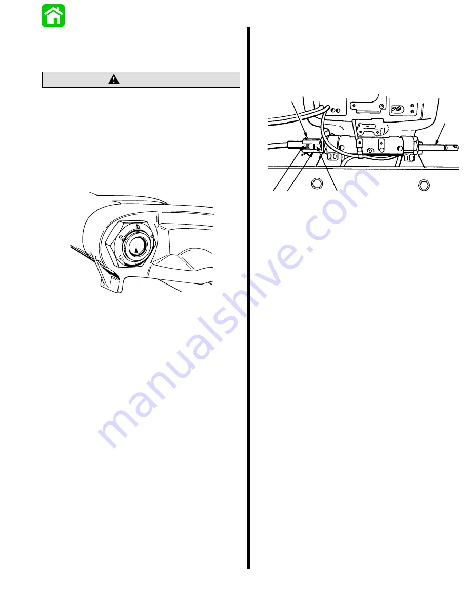
4. Install rubber bumper on inside of locking sleeve,
then install locking sleeve over steering cable at-
taching nut ) and secure with cotter pin . Spread
ends of cotter pin. Be sure to install cotter pin so
that it is located in-between attaching nut and
grease fitting , as shown.
50130
a
b
c
d
e
a - Cable Nut
b - Locking Sleeve
c - Cotter Key
d - Grease Fitting
e - Steering Cable
Содержание 100
Страница 4: ...GENERAL INFORMATION AND SPECIFICATIONS 1 ...
Страница 18: ...IGNITION SYSTEM ELECTRICAL AND IGNITION A 2 ...
Страница 30: ...11669 BATTERY CHARGING SYSTEM AND STARTING SYSTEM ELECTRICAL AND IGNITION B 2 ...
Страница 58: ...22480 TIMING SYNCHRONIZING ADJUSTING ELECTRICAL AND IGNITION C 2 ...
Страница 71: ...WIRING DIAGRAMS ELECTRICAL AND IGNITION D 2 ...
Страница 86: ...FUEL SYSTEM AND CARBURETION A 3 ...
Страница 118: ...OIL INJECTION SYSTEM B 3 ...
Страница 127: ...20032 3 CYLINDER ENGINES POWERHEAD A 4 ...
Страница 168: ...791 H GEAR HOUSING LOWER UNIT A 5 ...
Страница 170: ...5A 1 90 13645 2 1095 LOWER UNIT Notes ...
Страница 205: ...MID SECTION LOWER UNIT B 5 ...
Страница 207: ...5B 1 90 13645 2 495 LOWER UNIT Notes ...
Страница 218: ...SHOCK ABSORBER LOWER UNIT C 5 ...
Страница 223: ...17250 DESIGN I SIDE FILL RESERVOIR POWER TRIM A 6 ...
Страница 233: ...6A 9 POWER TRIM 90 13645 2 495 Commander Side Mount Remote Control Wiring Diagram ...
Страница 268: ...DESIGN II AFT FILL RESERVOIR POWER TRIM B 6 51344 ...
Страница 305: ...SINGLE RAM POWER TRIM C 6 51485 ...
Страница 309: ...6C 3 90 13645 2 495 POWER TRIM Notes ...
Страница 340: ...50099 ENGINE ATTACHMENTS ENGINE INSTALLATION 7 A ...
Страница 369: ...TILLER HANDLE AND CO PILOT OUTBOARD MOTOR INSTALLATION ATTACHMENTS 7 B ...
Страница 371: ...7B 1 90 13645 2 495 OUTBOARD MOTOR INSTALLATION ATTACHMENTS Notes ...