


90-13645--2
1095
5A-19
LOWER UNIT
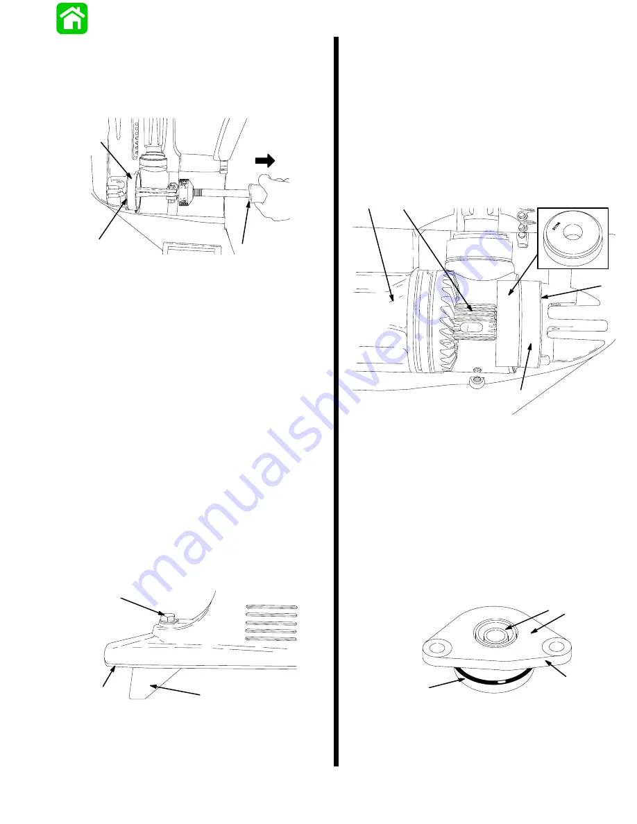
Forward Gear Bearing Race
IMPORTANT: Retain shim(s) for reassembly.
1. Remove race and shim(s) using Slide
Hammer (91-34569A1).
27653
a
b
c
a - Race
b - Shim(s)
c - Slide Hammer (91-34569A1)
Trim Tab Adjustment and Replacement
IMPORTANT: The trim tab is made of a special
alloy to aid in protecting the drive shaft housing
and gear housing from galvanic corrosion (corro-
sion and pitting of metal surfaces). Do not paint or
place protective coating on the trim tab, or trim
tab corrosion protection function will be lost.
1. Replace trim tab if 50% (or more) consumed.
Mark location of old trim tab on anti-ventilation
plate before removal; install new trim tab in same
location.
2. The trim tab provides a means to offset (balance)
some of the “steering load” that is caused by “pro-
peller torque” at higher operating speeds. If at
higher speeds the boat turns more easily to the
left, loosen bolt, move the trim tab (trailing edge)
to the left (when viewed from behind); retighten
bolt. Turn trim tab (trailing edge) to the right if the
boat turns more easily to the right.
19172
a
b
c
a - Trim Tab
b - Anti-Ventilation Plate
c - Retaining Bolt and Washer; Torque Bolt to 22 lbs. ft.
(29.8 N
m)
Reassembly
Forward Gear Bearing Race
1. Place shim(s) (retained from disassembly) into
housing. If shim(s) were lost, or a new gear hous-
ing is being assembled, start with 0.010
(0.254mm) shim(s).
2. Assemble components as shown; drive race into
housing by striking propeller shaft end with lead
hammer.
19179
a
b
d
e
c
a - Shim(s)
b - Race, Apply Quicksilver
Needle Bearing Assembly
Lubricant on O.D.
c - Mandrel (91-31106)
d - Disassembled Propeller
Shaft
e - Assembled Bearing
Carrier
Shift Shaft
1. Apply Loctite 271 on O.D. of new seal.
2. Press seal into shift shaft bushing until seal is
flush with surface.
3. Install new O-ring.
4. Apply 2-4-C with Teflon on O-ring and I.D. of seal.
19199
a
b
c
d
a - Seal
b - Bushing
c - Surface
d - O-ring
Содержание 100
Страница 4: ...GENERAL INFORMATION AND SPECIFICATIONS 1 ...
Страница 18: ...IGNITION SYSTEM ELECTRICAL AND IGNITION A 2 ...
Страница 30: ...11669 BATTERY CHARGING SYSTEM AND STARTING SYSTEM ELECTRICAL AND IGNITION B 2 ...
Страница 58: ...22480 TIMING SYNCHRONIZING ADJUSTING ELECTRICAL AND IGNITION C 2 ...
Страница 71: ...WIRING DIAGRAMS ELECTRICAL AND IGNITION D 2 ...
Страница 86: ...FUEL SYSTEM AND CARBURETION A 3 ...
Страница 118: ...OIL INJECTION SYSTEM B 3 ...
Страница 127: ...20032 3 CYLINDER ENGINES POWERHEAD A 4 ...
Страница 168: ...791 H GEAR HOUSING LOWER UNIT A 5 ...
Страница 170: ...5A 1 90 13645 2 1095 LOWER UNIT Notes ...
Страница 205: ...MID SECTION LOWER UNIT B 5 ...
Страница 207: ...5B 1 90 13645 2 495 LOWER UNIT Notes ...
Страница 218: ...SHOCK ABSORBER LOWER UNIT C 5 ...
Страница 223: ...17250 DESIGN I SIDE FILL RESERVOIR POWER TRIM A 6 ...
Страница 233: ...6A 9 POWER TRIM 90 13645 2 495 Commander Side Mount Remote Control Wiring Diagram ...
Страница 268: ...DESIGN II AFT FILL RESERVOIR POWER TRIM B 6 51344 ...
Страница 305: ...SINGLE RAM POWER TRIM C 6 51485 ...
Страница 309: ...6C 3 90 13645 2 495 POWER TRIM Notes ...
Страница 340: ...50099 ENGINE ATTACHMENTS ENGINE INSTALLATION 7 A ...
Страница 369: ...TILLER HANDLE AND CO PILOT OUTBOARD MOTOR INSTALLATION ATTACHMENTS 7 B ...
Страница 371: ...7B 1 90 13645 2 495 OUTBOARD MOTOR INSTALLATION ATTACHMENTS Notes ...