


90-13645--2
1095
5A-27
LOWER UNIT
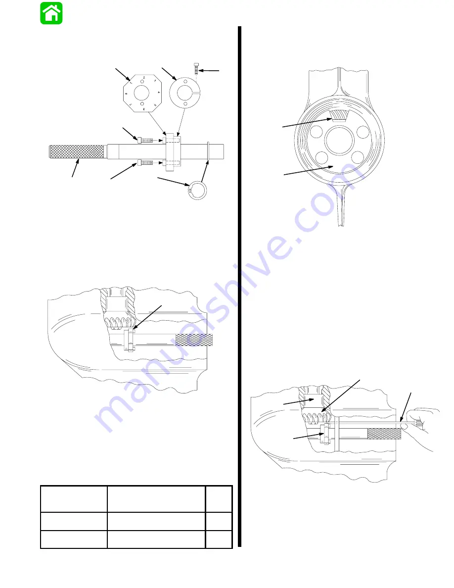
6. Assembly Pinion Gear Locating Tool (91-12349A2)
as shown; do not tighten collar retaining bolt at
this time.
a
b
c
e
f
c
d
a - Arbor
b - Gauging Block; Install With Numbers Away From Split Collar
c - Bolt; Gauging Block Retaining
d - Split Collar
e - Bolt; Collar Retaining
f - Snap Ring
7. Insert tool into forward gear assembly; position
gauging block under pinion gear as shown.
22067
a
a - Gauging Block
8. Remove tool, taking care not to change gauging
block position, and tighten collar retaining bolt.
9. Insert tool into forward gear assembly; position
proper numbered flat (from chart) of gauging
block – under pinion gear.
MODEL
GEAR RATIO
(PINION GEAR TEETH/
REVERSE GEAR TEETH)
USE
FLAT
NO.
75-thru-90
(3 Cylinder)
13/30
8
100/115/125
(4 Cylinder)
14/29
2
10. Install the number “3” locating disc against bear-
ing carrier shoulder in gear housing.
11. Position access hole as shown.
24643
a
b
a - Locating Disc
b - Access Hole
12. Determine pinion gear depth by inserting a feeler
gauge thru access hole in locating disc.
13. The correct clearance between gauging block
and pinion gear is 0.025
(0.64mm).
14. If clearance is correct, leave Bearing Preload Tool
on drive shaft and proceed to “Determining For-
ward Gear Backlash,” following.
15. If clearance is incorrect, add (or subtract) shims
from above bearing race to lower (or raise) pinion
gear. When reinstalling pinion nut, apply Loctite
271 on threads of nut.
24643
a
b
c
d
a - Feeler Gauge
b - Gauging Block
c - Pinion Gear
d - Bearing Race
Содержание 100
Страница 4: ...GENERAL INFORMATION AND SPECIFICATIONS 1 ...
Страница 18: ...IGNITION SYSTEM ELECTRICAL AND IGNITION A 2 ...
Страница 30: ...11669 BATTERY CHARGING SYSTEM AND STARTING SYSTEM ELECTRICAL AND IGNITION B 2 ...
Страница 58: ...22480 TIMING SYNCHRONIZING ADJUSTING ELECTRICAL AND IGNITION C 2 ...
Страница 71: ...WIRING DIAGRAMS ELECTRICAL AND IGNITION D 2 ...
Страница 86: ...FUEL SYSTEM AND CARBURETION A 3 ...
Страница 118: ...OIL INJECTION SYSTEM B 3 ...
Страница 127: ...20032 3 CYLINDER ENGINES POWERHEAD A 4 ...
Страница 168: ...791 H GEAR HOUSING LOWER UNIT A 5 ...
Страница 170: ...5A 1 90 13645 2 1095 LOWER UNIT Notes ...
Страница 205: ...MID SECTION LOWER UNIT B 5 ...
Страница 207: ...5B 1 90 13645 2 495 LOWER UNIT Notes ...
Страница 218: ...SHOCK ABSORBER LOWER UNIT C 5 ...
Страница 223: ...17250 DESIGN I SIDE FILL RESERVOIR POWER TRIM A 6 ...
Страница 233: ...6A 9 POWER TRIM 90 13645 2 495 Commander Side Mount Remote Control Wiring Diagram ...
Страница 268: ...DESIGN II AFT FILL RESERVOIR POWER TRIM B 6 51344 ...
Страница 305: ...SINGLE RAM POWER TRIM C 6 51485 ...
Страница 309: ...6C 3 90 13645 2 495 POWER TRIM Notes ...
Страница 340: ...50099 ENGINE ATTACHMENTS ENGINE INSTALLATION 7 A ...
Страница 369: ...TILLER HANDLE AND CO PILOT OUTBOARD MOTOR INSTALLATION ATTACHMENTS 7 B ...
Страница 371: ...7B 1 90 13645 2 495 OUTBOARD MOTOR INSTALLATION ATTACHMENTS Notes ...