


6B-34
90-13645--2
495
POWER TRIM
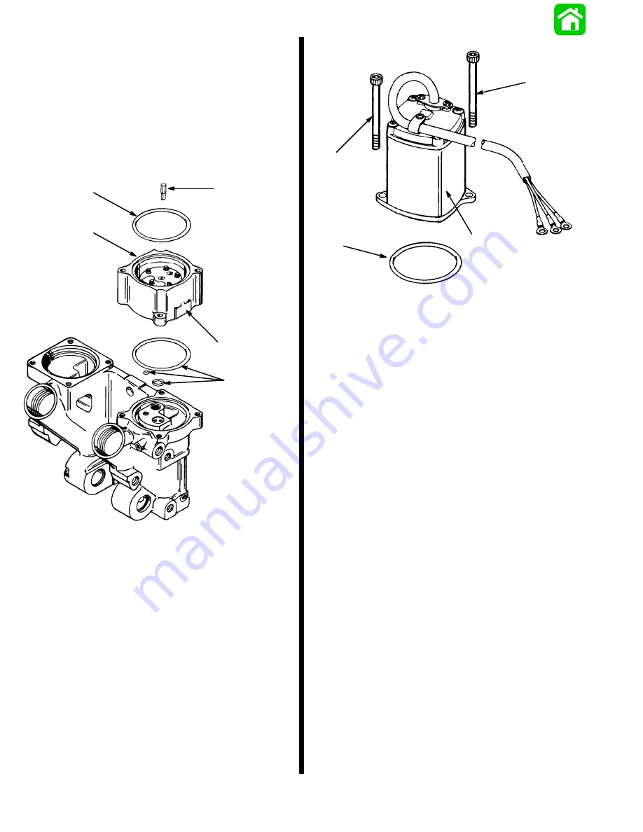
Reassembly - Motor and Pump
NOTE: Driveshaft is a loose part and may fall out of
position.
1. Install pump onto power trim manifold. Insure
O-rings are in proper locations. Secure with two
(2) screws. Torque screws to 70 lb. in. (7.9 N·m).
IMPORTANT: Install pump with location flat facing
towards starboard transom bracket.
51433
a
b
c
d
c
a - Pump (Flat towards starboard transom bracket)
b - Flat (Faces starboard transom bracket)
c - O-rings (4)
d - Driveshaft (Install in center hole in pump)
2. Fill pump with Quicksilver Power Trim and Steer-
ing Fluid prior to installing motor.
3. Install motor, secure with two (2) screws. Route
wiring; refer to Wiring Diagrams in this service
manual. Torque screws to 70 lb. in. (7.9 N·m).
NOTE: Insure motor and driveshaft are aligned.
51433
a
b
c
c
a - Motor
b - O-ring
c - Screw (2) - Torque screws to 70 lb. in. (7.9 N·m)
4. Complete reassembly of Power Trim System as
outlined in “Installation” on page 6B-15 and
6B-16.
Priming Power Trim System
1. Fill system with Quicksilver Power Trim and Steer-
ing Fluid or Automatic Transmission Fluid (ATF)
Type F or FA. Refer to “Fill, Check, and Purge”
on page 6B-5.
IMPORTANT: Run Trim System in short “jogs”
until pump motor primes and trim system moves.
If trim motor is run without priming pump,
driveshaft failure could result.
Trim Sender (Optional Accessory) Test
1. Check trim sender black lead for proper ground.
2. Trim outboard to full “DOWN” position.
3. Place ignition switch to “ON” position.
4. Connect Ohmmeter (R x 1 scale) leads between
outboard ground and Point 1.
5. Depress “UP” button. Ohmmeter needle should
move as the outboard is trimmed up. If needle
does not move, trim sender is defective.
Содержание 100
Страница 4: ...GENERAL INFORMATION AND SPECIFICATIONS 1 ...
Страница 18: ...IGNITION SYSTEM ELECTRICAL AND IGNITION A 2 ...
Страница 30: ...11669 BATTERY CHARGING SYSTEM AND STARTING SYSTEM ELECTRICAL AND IGNITION B 2 ...
Страница 58: ...22480 TIMING SYNCHRONIZING ADJUSTING ELECTRICAL AND IGNITION C 2 ...
Страница 71: ...WIRING DIAGRAMS ELECTRICAL AND IGNITION D 2 ...
Страница 86: ...FUEL SYSTEM AND CARBURETION A 3 ...
Страница 118: ...OIL INJECTION SYSTEM B 3 ...
Страница 127: ...20032 3 CYLINDER ENGINES POWERHEAD A 4 ...
Страница 168: ...791 H GEAR HOUSING LOWER UNIT A 5 ...
Страница 170: ...5A 1 90 13645 2 1095 LOWER UNIT Notes ...
Страница 205: ...MID SECTION LOWER UNIT B 5 ...
Страница 207: ...5B 1 90 13645 2 495 LOWER UNIT Notes ...
Страница 218: ...SHOCK ABSORBER LOWER UNIT C 5 ...
Страница 223: ...17250 DESIGN I SIDE FILL RESERVOIR POWER TRIM A 6 ...
Страница 233: ...6A 9 POWER TRIM 90 13645 2 495 Commander Side Mount Remote Control Wiring Diagram ...
Страница 268: ...DESIGN II AFT FILL RESERVOIR POWER TRIM B 6 51344 ...
Страница 305: ...SINGLE RAM POWER TRIM C 6 51485 ...
Страница 309: ...6C 3 90 13645 2 495 POWER TRIM Notes ...
Страница 340: ...50099 ENGINE ATTACHMENTS ENGINE INSTALLATION 7 A ...
Страница 369: ...TILLER HANDLE AND CO PILOT OUTBOARD MOTOR INSTALLATION ATTACHMENTS 7 B ...
Страница 371: ...7B 1 90 13645 2 495 OUTBOARD MOTOR INSTALLATION ATTACHMENTS Notes ...