


4A-32
90-13645--2
395
POWERHEAD
IMPORTANT: On some engines, BOTH the piston
rod and rod cap bolt holes are threaded. The rod
cap and rod must be aligned and held tight
together when threading in bolt. Check that
mating surfaces are tight together after bolt
enters the threads in the piston rod.
20033
Connecting Rod Cap Alignment
1. Check each connecting rod for correct alignment
by carefully running fingernails up and down edge
of rod cap. If not aligned, a ridge can be seen or
felt at the separating line. Correct any misalign-
ment.
Front View
Correct
Front View
Incorrect
Side View
Correct
Side View
Incorrect
Side View
Incorrect
Space
Ridge
51224
2. When connecting rods are attached, and bolts
drawn down finger tight, torque rod-cap bolts to
15 lb. in. (1.7 N
m). Recheck alignment. Retorque
1/4 in. bolts to 15 lb. ft. (20.3 N
m) or 5/16 in.
bolts to 30 lb. ft. (40.7 N
m). Recheck alignment.
Turn each rod-cap bolt 90
_
further after 30 lb. ft.
reading is acquired.
S
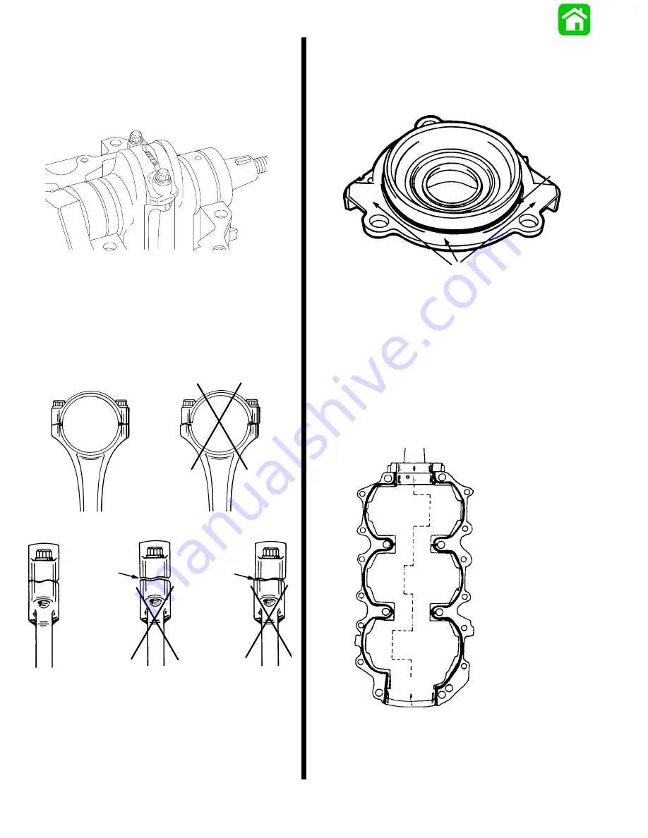
Replace lower crankshaft End Cap.
1. Coat mating surface with Perfect Seal. DO NOT
coat O-ring seal.
2. Bolt to block (2 bolts) - finger tighten - lightly.
19336
a
b
a - Mating Surface
b - O-ring Seal
Crankcase Cover to Block
LOCTITE MASTER GASKET SEALANT,.
92-12564-1 is used; it comes as a kit, which includes
Primer and Sealant. Instructions contained in the kit
MUST BE FOLLOWED EXACTLY. (Clean both sur-
faces).
IMPORTANT: Extend sealer to edge on each center
main journal to prevent blow-by between cylinders.
Sealant “Bead Pattern”
indicated by bold line.
Содержание 100
Страница 4: ...GENERAL INFORMATION AND SPECIFICATIONS 1 ...
Страница 18: ...IGNITION SYSTEM ELECTRICAL AND IGNITION A 2 ...
Страница 30: ...11669 BATTERY CHARGING SYSTEM AND STARTING SYSTEM ELECTRICAL AND IGNITION B 2 ...
Страница 58: ...22480 TIMING SYNCHRONIZING ADJUSTING ELECTRICAL AND IGNITION C 2 ...
Страница 71: ...WIRING DIAGRAMS ELECTRICAL AND IGNITION D 2 ...
Страница 86: ...FUEL SYSTEM AND CARBURETION A 3 ...
Страница 118: ...OIL INJECTION SYSTEM B 3 ...
Страница 127: ...20032 3 CYLINDER ENGINES POWERHEAD A 4 ...
Страница 168: ...791 H GEAR HOUSING LOWER UNIT A 5 ...
Страница 170: ...5A 1 90 13645 2 1095 LOWER UNIT Notes ...
Страница 205: ...MID SECTION LOWER UNIT B 5 ...
Страница 207: ...5B 1 90 13645 2 495 LOWER UNIT Notes ...
Страница 218: ...SHOCK ABSORBER LOWER UNIT C 5 ...
Страница 223: ...17250 DESIGN I SIDE FILL RESERVOIR POWER TRIM A 6 ...
Страница 233: ...6A 9 POWER TRIM 90 13645 2 495 Commander Side Mount Remote Control Wiring Diagram ...
Страница 268: ...DESIGN II AFT FILL RESERVOIR POWER TRIM B 6 51344 ...
Страница 305: ...SINGLE RAM POWER TRIM C 6 51485 ...
Страница 309: ...6C 3 90 13645 2 495 POWER TRIM Notes ...
Страница 340: ...50099 ENGINE ATTACHMENTS ENGINE INSTALLATION 7 A ...
Страница 369: ...TILLER HANDLE AND CO PILOT OUTBOARD MOTOR INSTALLATION ATTACHMENTS 7 B ...
Страница 371: ...7B 1 90 13645 2 495 OUTBOARD MOTOR INSTALLATION ATTACHMENTS Notes ...