


6A-14
POWER TRIM
90-13645--2
495
Battery Voltage Indicated:
D
Check “Down” solenoid terminals for
loose or corroded connections.
D
Check BLACK ground wire (on “Down”
solenoid) for corrosion or open.
D
Test “Down” solenoid. Refer to “Motor and
Electrical Tests,” see Index.
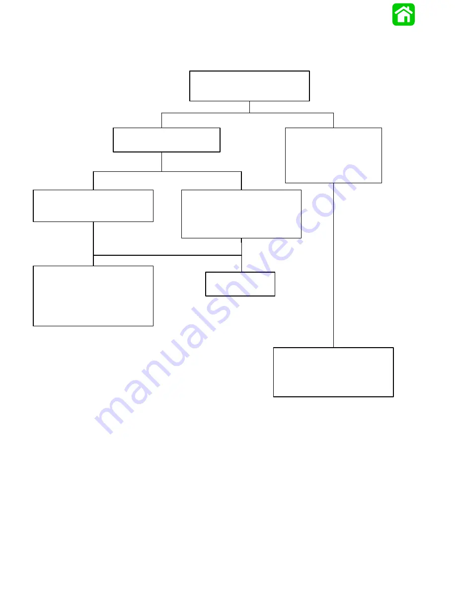
Troubleshooting the “Down” Circuit
(When “Up” Circuit Is OK)
Connect Voltmeter RED lead to Point 1 and
BLACK lead to ground.
Depress the “Down” trim button.
No Voltage Indicated:
Connect Voltmeter RED lead to
Point 4 and BLACK lead to
ground. Depress “Down” trim
button. If battery voltage is
indicated, wire is open between
Points 4 and 1.
Battery Voltage Indicated:
D
Connect Voltmeter RED lead to Point 2.
D
Depress “Down” trim button.
No Voltage Indicated:
Connect Voltmeter RED lead to Point 5. If
battery voltage is indicated, trim switch is
faulty. If no battery voltage, check for loose
or corroded connection at Point 5 or open
circuit in wire supplying current to Point 5.
Battery Voltage Indicated:
Connect Voltmeter RED lead to Point 9.
No Voltage Indicated:
There is an open circuit between Point 9 and
positive (+) battery terminal.
D
Check for loose or corroded connections.
D
Check wires for open.
No Voltage Indicated:
Solenoid is defective.
Remote Controls With or Without Trailer Buttons
Содержание 100
Страница 4: ...GENERAL INFORMATION AND SPECIFICATIONS 1 ...
Страница 18: ...IGNITION SYSTEM ELECTRICAL AND IGNITION A 2 ...
Страница 30: ...11669 BATTERY CHARGING SYSTEM AND STARTING SYSTEM ELECTRICAL AND IGNITION B 2 ...
Страница 58: ...22480 TIMING SYNCHRONIZING ADJUSTING ELECTRICAL AND IGNITION C 2 ...
Страница 71: ...WIRING DIAGRAMS ELECTRICAL AND IGNITION D 2 ...
Страница 86: ...FUEL SYSTEM AND CARBURETION A 3 ...
Страница 118: ...OIL INJECTION SYSTEM B 3 ...
Страница 127: ...20032 3 CYLINDER ENGINES POWERHEAD A 4 ...
Страница 168: ...791 H GEAR HOUSING LOWER UNIT A 5 ...
Страница 170: ...5A 1 90 13645 2 1095 LOWER UNIT Notes ...
Страница 205: ...MID SECTION LOWER UNIT B 5 ...
Страница 207: ...5B 1 90 13645 2 495 LOWER UNIT Notes ...
Страница 218: ...SHOCK ABSORBER LOWER UNIT C 5 ...
Страница 223: ...17250 DESIGN I SIDE FILL RESERVOIR POWER TRIM A 6 ...
Страница 233: ...6A 9 POWER TRIM 90 13645 2 495 Commander Side Mount Remote Control Wiring Diagram ...
Страница 268: ...DESIGN II AFT FILL RESERVOIR POWER TRIM B 6 51344 ...
Страница 305: ...SINGLE RAM POWER TRIM C 6 51485 ...
Страница 309: ...6C 3 90 13645 2 495 POWER TRIM Notes ...
Страница 340: ...50099 ENGINE ATTACHMENTS ENGINE INSTALLATION 7 A ...
Страница 369: ...TILLER HANDLE AND CO PILOT OUTBOARD MOTOR INSTALLATION ATTACHMENTS 7 B ...
Страница 371: ...7B 1 90 13645 2 495 OUTBOARD MOTOR INSTALLATION ATTACHMENTS Notes ...