


4A-25
90-13645--2
495
POWERHEAD
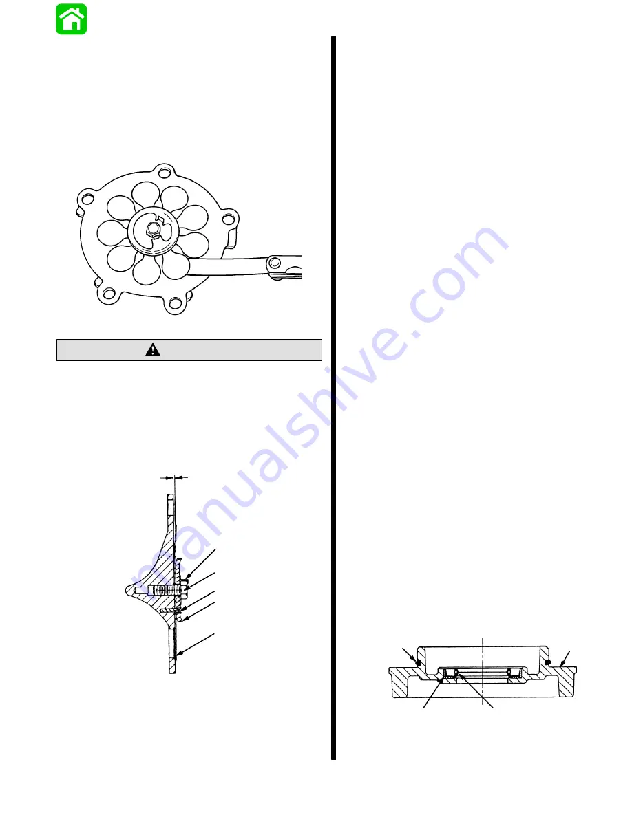
There are 3 reed segments. Reed should lie flat.
There should be no preload (pressure between reed
and reed-block), but a slight preload is tolerable.
The maximum allowable opening between reed and
reed-block is 0.020 (in.). This must be checked with
a flat blade feeler gauge, as shown.
If the opening exceeds 0.020 (in.), or if the reed is
chipped, cracked, or otherwise damaged, replace.
19337
Replace Locking Tab-Washer. DO NOT REUSE.
CAUTION
If reed block was disassembled, reassemble by locat-
ing reeds on pins with retaining washer . Use new tab
washer. Insert bolt, and torque to 80 lb. in. (9.0 N
m);
then, if necessary, continue the torque to align flat on
hex-head to locking tab - Do not exceed 100 lb. in.
(11.3 N
m) torque. Bend up tab to secure bolt position.
a
b
c
d
e
0.020 MAX.
a - Reeds
b - Retaining Washer
c - Pins
d - Bolt
e - Locking Tab
Powerhead Reassembly and
Installation
General Information
Before proceeding with powerhead reassembly, be
sure that all parts to be reused have been carefully
cleaned and thoroughly inspected, as outlined in
“Cleaning and Inspection”. Parts, which have not
been properly cleaned (or which are questionable),
can severely damage an otherwise perfectly good
powerhead within a few minutes of operation. All
new powerhead gaskets must be installed during
assembly.
During reassembly, lubricate parts with Quicksilver
2-Cycle Outboard Oil whenever 2-cycle oil is specified
and Quicksilver 2-4-C W/Teflon whenever grease is
specified.
A torque wrench is essential for correct reassembly of
powerhead. Do not attempt to reassemble power-
head without using a torque wrench.
EXAMPLE: If Exhaust Cover bolts require a torque of
220 lb. in. (24.9 N
m), (a) tighten all bolts to
73 lb. in. (8.2 N
m), following specified torque
sequence, (b) tighten all bolts to 146 lb. in. (16.6 N
m),
following torque sequence, then finally, (c) tighten all
bolts to 220 lb. in. (24.9 N
m), following torque
sequence.
End Cap
Clean thoroughly, including seal and O-ring seats; re-
move perfect seal residue and clean cap-to-head
mating surfaces.
Apply a thin bead of Loctite 271 to outer face on end
cap oil seal. Wipe off excess Loctite after installing.
Using suitable mandrel, press oil seal into cap until
fully seated. Remove any excess Loctite.
NOTE: Lip of seal goes in.
Lubricate oil seal lip with 2-4-C w/Teflon.
Lubricate O-ring seal with 2-4-C w/Teflon; install in
groove.
a
c
b
d
a - Outer Face
b - O–Ring
c - Seal Lip
d - Mating Surface
Содержание 100
Страница 4: ...GENERAL INFORMATION AND SPECIFICATIONS 1 ...
Страница 18: ...IGNITION SYSTEM ELECTRICAL AND IGNITION A 2 ...
Страница 30: ...11669 BATTERY CHARGING SYSTEM AND STARTING SYSTEM ELECTRICAL AND IGNITION B 2 ...
Страница 58: ...22480 TIMING SYNCHRONIZING ADJUSTING ELECTRICAL AND IGNITION C 2 ...
Страница 71: ...WIRING DIAGRAMS ELECTRICAL AND IGNITION D 2 ...
Страница 86: ...FUEL SYSTEM AND CARBURETION A 3 ...
Страница 118: ...OIL INJECTION SYSTEM B 3 ...
Страница 127: ...20032 3 CYLINDER ENGINES POWERHEAD A 4 ...
Страница 168: ...791 H GEAR HOUSING LOWER UNIT A 5 ...
Страница 170: ...5A 1 90 13645 2 1095 LOWER UNIT Notes ...
Страница 205: ...MID SECTION LOWER UNIT B 5 ...
Страница 207: ...5B 1 90 13645 2 495 LOWER UNIT Notes ...
Страница 218: ...SHOCK ABSORBER LOWER UNIT C 5 ...
Страница 223: ...17250 DESIGN I SIDE FILL RESERVOIR POWER TRIM A 6 ...
Страница 233: ...6A 9 POWER TRIM 90 13645 2 495 Commander Side Mount Remote Control Wiring Diagram ...
Страница 268: ...DESIGN II AFT FILL RESERVOIR POWER TRIM B 6 51344 ...
Страница 305: ...SINGLE RAM POWER TRIM C 6 51485 ...
Страница 309: ...6C 3 90 13645 2 495 POWER TRIM Notes ...
Страница 340: ...50099 ENGINE ATTACHMENTS ENGINE INSTALLATION 7 A ...
Страница 369: ...TILLER HANDLE AND CO PILOT OUTBOARD MOTOR INSTALLATION ATTACHMENTS 7 B ...
Страница 371: ...7B 1 90 13645 2 495 OUTBOARD MOTOR INSTALLATION ATTACHMENTS Notes ...