


7A-22
ENGINE ATTACHMENTS
90-13645--2
495
Normal Service – Every 50 hrs. of operation or 60
days (whichever comes first)
*Severe Service – Every 25 hrs. of operation or 30
days (whichever comes first)
*
Operation in a salt water area is considered “Severe Service.”
1. Carefully check steering system components for
wear. Replace worn parts.
2. Check steering system fasteners to be sure that
they are torqued to correct specifications.
Ride-Guide steering cables are lubricated at the fac-
tory and require no additional lubrication at initial
installation.
WARNING
Core of each steering cable (transom end) must
be fully retracted into cable housing before
lubricating cable. If cable is lubricated while
extended, hydraulic lock could occur.
3. With core of Ride-Guide steering cable (transom
end) fully retracted, lubricate transom end of
steering cables thru grease fittings with 2-4-C w/
Teflon. Lubricate exposed portion of cable ends
with 2-4-C w/Teflon.
4. Lubricate pivot point of steering link rod and ball
joint of link rod/steering coupler with SAE 30W
Motor Oil.
5. Inspection and lubrication of steering head
assembly (rotary or straight rack) should be
performed once each year (by your Authorized
Dealer) or whenever steering mount and/or
steering head are disassembled, or if steering
effort has increased. Lubricate with 2-4-C
w/Teflon.
50135
a
b
d
c
a - Grease Fitting
b - Cable Ends
c - Pivot Point
d - Ball Joint
Remote Control Installation
Shift Cable Installation and
Adjustment to Engine
IMPORTANT: Install control cables to remote con-
trol and mount remote control BEFORE attaching
control cables to engine.
NOTE: Attach shift cable to engine first. Shift cable is
the first cable to move when remote control handle is
advanced from neutral position toward in-gear
position.
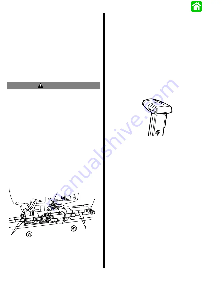
If remote control has a neutral lock release, secure
the release in the depressed position using a piece of
tape, as shown. Now you can locate the true neutral
detent.
22752
NOTE: Rotate remote control handle back and forth.
You will feel three detent positions; center detent is
neutral.
1. Position remote control handle in neutral detent.
2. Manually shift engine into neutral (propeller will
rotate freely).
Содержание 100
Страница 4: ...GENERAL INFORMATION AND SPECIFICATIONS 1 ...
Страница 18: ...IGNITION SYSTEM ELECTRICAL AND IGNITION A 2 ...
Страница 30: ...11669 BATTERY CHARGING SYSTEM AND STARTING SYSTEM ELECTRICAL AND IGNITION B 2 ...
Страница 58: ...22480 TIMING SYNCHRONIZING ADJUSTING ELECTRICAL AND IGNITION C 2 ...
Страница 71: ...WIRING DIAGRAMS ELECTRICAL AND IGNITION D 2 ...
Страница 86: ...FUEL SYSTEM AND CARBURETION A 3 ...
Страница 118: ...OIL INJECTION SYSTEM B 3 ...
Страница 127: ...20032 3 CYLINDER ENGINES POWERHEAD A 4 ...
Страница 168: ...791 H GEAR HOUSING LOWER UNIT A 5 ...
Страница 170: ...5A 1 90 13645 2 1095 LOWER UNIT Notes ...
Страница 205: ...MID SECTION LOWER UNIT B 5 ...
Страница 207: ...5B 1 90 13645 2 495 LOWER UNIT Notes ...
Страница 218: ...SHOCK ABSORBER LOWER UNIT C 5 ...
Страница 223: ...17250 DESIGN I SIDE FILL RESERVOIR POWER TRIM A 6 ...
Страница 233: ...6A 9 POWER TRIM 90 13645 2 495 Commander Side Mount Remote Control Wiring Diagram ...
Страница 268: ...DESIGN II AFT FILL RESERVOIR POWER TRIM B 6 51344 ...
Страница 305: ...SINGLE RAM POWER TRIM C 6 51485 ...
Страница 309: ...6C 3 90 13645 2 495 POWER TRIM Notes ...
Страница 340: ...50099 ENGINE ATTACHMENTS ENGINE INSTALLATION 7 A ...
Страница 369: ...TILLER HANDLE AND CO PILOT OUTBOARD MOTOR INSTALLATION ATTACHMENTS 7 B ...
Страница 371: ...7B 1 90 13645 2 495 OUTBOARD MOTOR INSTALLATION ATTACHMENTS Notes ...