


6A-36
POWER TRIM
90-13645--2
495
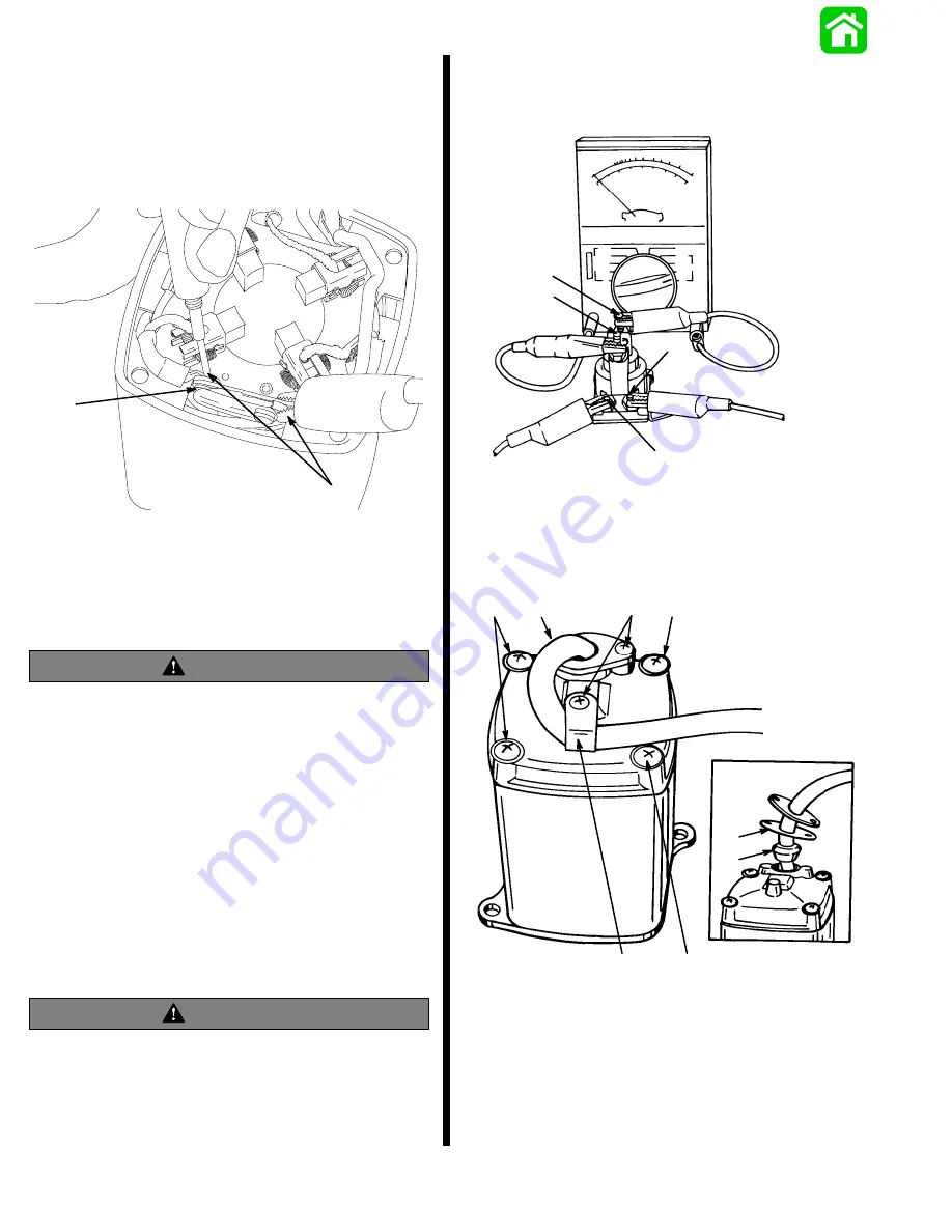
MOTOR DISASSEMBLED
Connect Ohmmeter (R x 1 scale) leads as shown. If
switch is good, full continuity (zero ohms) will be
indicated.
If full continuity is not indicated, clean switch contact
surfaces, using an ignition point file.
18473
a
b
c
d
c - Test Leads
d - Switch Contact Surface
Recheck switch; if full continuity is not indicated, re-
place brush card. Switch is supplied on brush card.
Trim Pump Motor Test
WARNING
Do not perform this test near flammables (or
explosives), as a spark may occur when making
connections.
1. Disconnect BLUE (motor) wire and BLACK (mo-
tor) wire at solenoids.
2. Connect a 12-volt supply to motor wires [POS-
ITIVE (+) wire to BLUE (motor) wire, and NEG-
ATIVE (–) wire to BLACK (motor) wire]. Motor
should run.
3. If motor does not run, disassemble motor and
check components. Refer to “Motor Repair,”
following.
Solenoid Test
WARNING
Do not perform this test near flammable materials,
as a spark may occur while making electrical
connections.
1. Disconnect all wires from solenoid terminals.
2. Set an Ohmmeter to R x 1 scale and connect me-
ter leads to solenoid terminals 1 and 2.
3. Connect a 12-volt power supply to terminals 3 and
4. Solenoid should click and meter should read
zero (0) ohms (full continuity).
51338
1
2
3
4
4. If meter does not read zero (0) ohms, replace
solenoid.
Motor Disassembly
1. Remove screws and clamp.
a
51345
a
b
d
e
a
b
c
a - Screw (4)
b - Screw (3)
c - Clamp
d - Gasket
e - Grommet
Содержание 100
Страница 4: ...GENERAL INFORMATION AND SPECIFICATIONS 1 ...
Страница 18: ...IGNITION SYSTEM ELECTRICAL AND IGNITION A 2 ...
Страница 30: ...11669 BATTERY CHARGING SYSTEM AND STARTING SYSTEM ELECTRICAL AND IGNITION B 2 ...
Страница 58: ...22480 TIMING SYNCHRONIZING ADJUSTING ELECTRICAL AND IGNITION C 2 ...
Страница 71: ...WIRING DIAGRAMS ELECTRICAL AND IGNITION D 2 ...
Страница 86: ...FUEL SYSTEM AND CARBURETION A 3 ...
Страница 118: ...OIL INJECTION SYSTEM B 3 ...
Страница 127: ...20032 3 CYLINDER ENGINES POWERHEAD A 4 ...
Страница 168: ...791 H GEAR HOUSING LOWER UNIT A 5 ...
Страница 170: ...5A 1 90 13645 2 1095 LOWER UNIT Notes ...
Страница 205: ...MID SECTION LOWER UNIT B 5 ...
Страница 207: ...5B 1 90 13645 2 495 LOWER UNIT Notes ...
Страница 218: ...SHOCK ABSORBER LOWER UNIT C 5 ...
Страница 223: ...17250 DESIGN I SIDE FILL RESERVOIR POWER TRIM A 6 ...
Страница 233: ...6A 9 POWER TRIM 90 13645 2 495 Commander Side Mount Remote Control Wiring Diagram ...
Страница 268: ...DESIGN II AFT FILL RESERVOIR POWER TRIM B 6 51344 ...
Страница 305: ...SINGLE RAM POWER TRIM C 6 51485 ...
Страница 309: ...6C 3 90 13645 2 495 POWER TRIM Notes ...
Страница 340: ...50099 ENGINE ATTACHMENTS ENGINE INSTALLATION 7 A ...
Страница 369: ...TILLER HANDLE AND CO PILOT OUTBOARD MOTOR INSTALLATION ATTACHMENTS 7 B ...
Страница 371: ...7B 1 90 13645 2 495 OUTBOARD MOTOR INSTALLATION ATTACHMENTS Notes ...