


7A-21
ENGINE ATTACHMENTS
90-13645--2
495
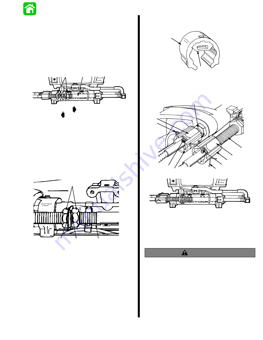
Loosen adjustment nuts and pull steering cable
mounting tube (by hand) away from end of steering
cable (to remove slack in steering system). Tighten
adjustment nuts against mounting bracket and check
system for slack (play). If steering system is too tight,
readjust tube toward end of steering cable or, if too
much slack (play) exists in system, readjust tube
away from end of steering cable. Tighten nuts against
mounting bracket and readjust, if necessary.
a
b
c
d
16961
a - Steering Cable Mounting Tube
b - Adjustment Nuts
c - Adjust Tube in This Direction to Remove Slack from Steering
System.
d - Adjust Tube in This Direction to Reduce Tension from
Steering System.
After steering system tension is adjusted correctly,
tighten adjustment nuts against mounting bracket, to
a torque of 35 Ib. ft. (47.4 N
m) and bend a tab lock
washer against a flat on each nut.
51887
a
b
c
c
a - Steering Cable Mounting Tube
b - Adjustment Nuts; Torque to 35 lb. ft. (47.4 N
m)
c - Tab Lock Washer (Bend Against Flat on Each Adjustment
Nut)
Tighten steering cable attaching nuts of each steering
cable to a torque of 35 Ib. ft. (47.4 N
m).
Install rubber bumpers (a) on inside of each locking
sleeve (b).
a
b
51889
Install locking sleeves over steering cable attaching
nuts and secure with cotter pins. Spread ends of cot-
ter pins. Be sure to install cotter pin so that it is located
in between attaching nut and grease fitting.
d
51890
a
b
c
e
c
a
b
d
f
51452
a - Steering Cable Attaching Nut - Torque to 35 lb. ft. (47.4 N
m)
b - Locking Sleeve (If So Equipped)
c - Cotter Pin
d - Grease Fitting
e - Steering Cable Mounting Tube
f - Outboard Tilt Tube
WARNING
After installation is complete (and before operating
outboard(s), check that boat will turn right when
steering wheel is turned right and that boat will turn
left when steering wheel is turned left. Check
steering thru full range (left and right) at all tilt
angles to assure interference-free movement.
Maintenance Instructions
Maintenance inspection is owner’s responsibility and
must be performed at intervals specified, following:
Содержание 100
Страница 4: ...GENERAL INFORMATION AND SPECIFICATIONS 1 ...
Страница 18: ...IGNITION SYSTEM ELECTRICAL AND IGNITION A 2 ...
Страница 30: ...11669 BATTERY CHARGING SYSTEM AND STARTING SYSTEM ELECTRICAL AND IGNITION B 2 ...
Страница 58: ...22480 TIMING SYNCHRONIZING ADJUSTING ELECTRICAL AND IGNITION C 2 ...
Страница 71: ...WIRING DIAGRAMS ELECTRICAL AND IGNITION D 2 ...
Страница 86: ...FUEL SYSTEM AND CARBURETION A 3 ...
Страница 118: ...OIL INJECTION SYSTEM B 3 ...
Страница 127: ...20032 3 CYLINDER ENGINES POWERHEAD A 4 ...
Страница 168: ...791 H GEAR HOUSING LOWER UNIT A 5 ...
Страница 170: ...5A 1 90 13645 2 1095 LOWER UNIT Notes ...
Страница 205: ...MID SECTION LOWER UNIT B 5 ...
Страница 207: ...5B 1 90 13645 2 495 LOWER UNIT Notes ...
Страница 218: ...SHOCK ABSORBER LOWER UNIT C 5 ...
Страница 223: ...17250 DESIGN I SIDE FILL RESERVOIR POWER TRIM A 6 ...
Страница 233: ...6A 9 POWER TRIM 90 13645 2 495 Commander Side Mount Remote Control Wiring Diagram ...
Страница 268: ...DESIGN II AFT FILL RESERVOIR POWER TRIM B 6 51344 ...
Страница 305: ...SINGLE RAM POWER TRIM C 6 51485 ...
Страница 309: ...6C 3 90 13645 2 495 POWER TRIM Notes ...
Страница 340: ...50099 ENGINE ATTACHMENTS ENGINE INSTALLATION 7 A ...
Страница 369: ...TILLER HANDLE AND CO PILOT OUTBOARD MOTOR INSTALLATION ATTACHMENTS 7 B ...
Страница 371: ...7B 1 90 13645 2 495 OUTBOARD MOTOR INSTALLATION ATTACHMENTS Notes ...