


7A-16
ENGINE ATTACHMENTS
90-13645--2
495
a
b
c
d
e
f
g
h
i
j
k
f
f
e
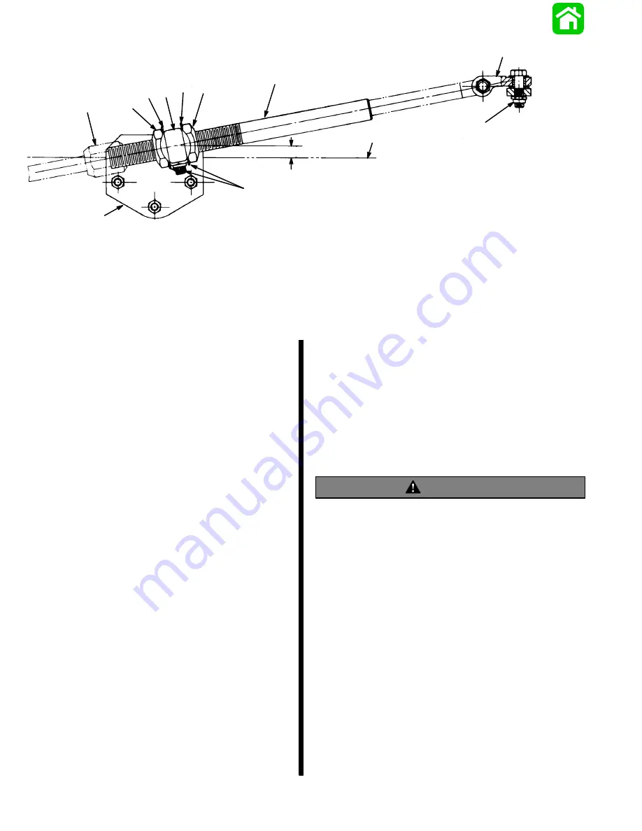
a - Ride-Guide Yoke
b - 0 in. to 1/2 in. (0mm to 12.8mm) (Center of Ride-Guide Yoke
to Top of Transom)
c - Top of Transom
d - Transom Bracket
e - Cable Tube Jam Nuts - Torque to 35 lbs. ft. (47.4 N·m)
f - Tab Washer
g - After Jam Nuts are Torqued to Specification, Bend Locking
Tabs against Nuts.
h - Cable Guide Tube
i - Ride-Guide Cable Attaching Nut - Torque to 35 lbs. ft.
(47.4 N
m)
j - “Clevis Kit”
k - Clevis Attaching Locknut - Torque to 20 lbs. ft. (27.1 N·m)
Figure 3
NOTE: When drilling thru transom, be sure that holes
are drilled perpendicular to transom.
6. With attaching kit positioned as outlined preced-
ing, use 3 holes in transom bracket as a guide and
drill three 11/32 in. (8.7mm) holes thru transom.
7. Use a marine-type sealer on three 5/16 in. x
3-1/4 in. (7.9mm x 82.6mm) bolts. Secure attach-
ing kit to transom, using transom backing plate, 3
bolts (with sealer) and 3 locknuts, installed as
shown in Figure 2. Torque locknuts to 10 Ibs. ft.
(13.5 N
m).
STEERING CABLE INSTALLATION
1. Lubricate steering cable end with Quicksilver
2-4-C w/Teflon.
2. Install steering cable thru steering cable tube and
secure to cable tube with cable attaching nut
(Figure 3). Do not tighten cable attaching nut at
this time.
3. Attach Ride-Guide cable to outboard steering
arm, using the proper “Clevis Kit.” Installation
instructions for clevis are with “Clevis Kit.”
4. Adjust 2 large jam nuts on cable tube of attaching
kit, so that steering wheel is in normal straight-
driving position with outboard in straight-running
position. Torque each jam nut to 35 lbs. ft. (47.4
N
m), then bend a side of tab washer against flat
of each jam nut (Figure 3).
5. Torque Ride-Guide cable attaching nut (which se-
cures cable to guide tube) to 35 lbs. ft. (47.4 N
m)
(Figure 3). Install locking sleeve over cable at-
taching nut and secure with cotter pin. Spread
ends of cotter pin.
NOTE: Some Ride-Guide steering cables may not be
equipped with locking sleeve and cotter pin. If cable
being installed does not have these parts, disregard
instructions to install them.
WARNING
After installation is completed (and before
operating outboard), check that boat will turn right
when steering wheel is turned right and that boat
will turn left when steering wheel is turned left.
Check steering thru full range (left and right) at all
tilt angles to assure interference-free movement.
Maintenance Instructions
Lubrication and maintenance inspection is owner’s
responsibility and must be performed at intervals spe-
cified, following:
Normal Service – Every 50 hrs. of operation or 60
days (whichever comes first)
*Severe Service – Every 25 hrs. of operation or 30
days (whichever comes first)
*
Operation in a salt water area is considered “Severe Service.”
Содержание 100
Страница 4: ...GENERAL INFORMATION AND SPECIFICATIONS 1 ...
Страница 18: ...IGNITION SYSTEM ELECTRICAL AND IGNITION A 2 ...
Страница 30: ...11669 BATTERY CHARGING SYSTEM AND STARTING SYSTEM ELECTRICAL AND IGNITION B 2 ...
Страница 58: ...22480 TIMING SYNCHRONIZING ADJUSTING ELECTRICAL AND IGNITION C 2 ...
Страница 71: ...WIRING DIAGRAMS ELECTRICAL AND IGNITION D 2 ...
Страница 86: ...FUEL SYSTEM AND CARBURETION A 3 ...
Страница 118: ...OIL INJECTION SYSTEM B 3 ...
Страница 127: ...20032 3 CYLINDER ENGINES POWERHEAD A 4 ...
Страница 168: ...791 H GEAR HOUSING LOWER UNIT A 5 ...
Страница 170: ...5A 1 90 13645 2 1095 LOWER UNIT Notes ...
Страница 205: ...MID SECTION LOWER UNIT B 5 ...
Страница 207: ...5B 1 90 13645 2 495 LOWER UNIT Notes ...
Страница 218: ...SHOCK ABSORBER LOWER UNIT C 5 ...
Страница 223: ...17250 DESIGN I SIDE FILL RESERVOIR POWER TRIM A 6 ...
Страница 233: ...6A 9 POWER TRIM 90 13645 2 495 Commander Side Mount Remote Control Wiring Diagram ...
Страница 268: ...DESIGN II AFT FILL RESERVOIR POWER TRIM B 6 51344 ...
Страница 305: ...SINGLE RAM POWER TRIM C 6 51485 ...
Страница 309: ...6C 3 90 13645 2 495 POWER TRIM Notes ...
Страница 340: ...50099 ENGINE ATTACHMENTS ENGINE INSTALLATION 7 A ...
Страница 369: ...TILLER HANDLE AND CO PILOT OUTBOARD MOTOR INSTALLATION ATTACHMENTS 7 B ...
Страница 371: ...7B 1 90 13645 2 495 OUTBOARD MOTOR INSTALLATION ATTACHMENTS Notes ...