


6C-10
90-13645--2
495
POWER-TRIM
Power Trim Partial Leak Down at
Maximum Trim
Power Trim Date Code 14182 and Below – Service
Bulletin No. 94-13.
Some units, when trimmed to the maximum 20 de-
gree limit, will leak down approximately 5 degrees
and then hold. The leak will ONLY occur while the
boat is under power. The cause for the 5 degree leak
down is the lack of a fluid passage between the shock
piston and the memory piston.
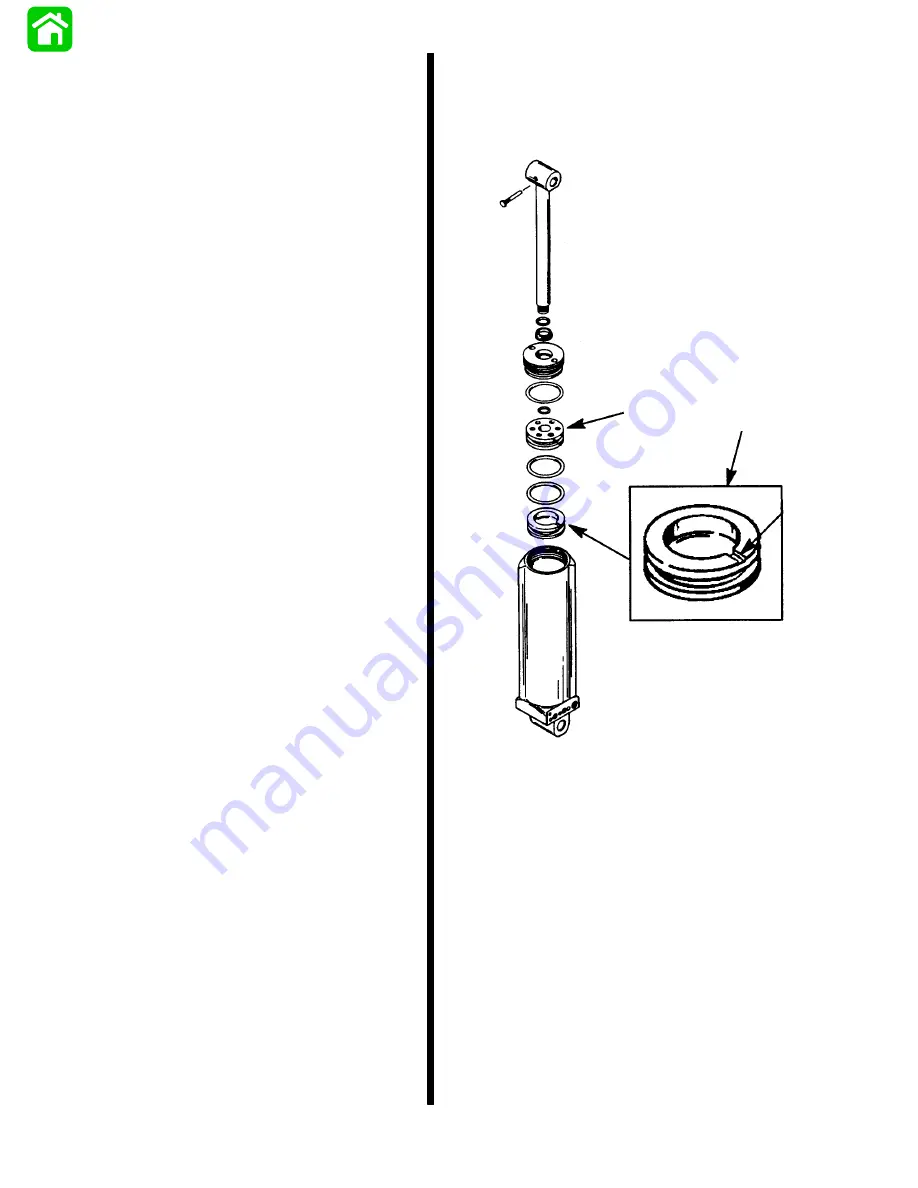
1. Disassemble the tilt ram assembly and remove
the memory piston.
2. Cut a small groove 0.020 –0.040 in. (0.5 –
1.0mm) deep across the top face of the memory
piston. The groove will allow oil passage when the
shock piston and memory piston are in contact.
The groove can be made with a hacksaw or trian-
gular file.
NOTE: Power trim assemblies with Date Code
14183 and ABOVE have a groove in the shock
piston to allow fluid passage. The memory piston
remains the same and does not have a groove
across the face.
3. Remove all burrs and filings from the memory pis-
ton.
4. Reassemble the trim/tilt ram assembly using new
o-rings and seals.
a
b
c
a - Shock Piston
b - Memory Piston
c - 0.020 – 0.040 in. (0.5 – 1.0mm) Groove
Содержание 100
Страница 4: ...GENERAL INFORMATION AND SPECIFICATIONS 1 ...
Страница 18: ...IGNITION SYSTEM ELECTRICAL AND IGNITION A 2 ...
Страница 30: ...11669 BATTERY CHARGING SYSTEM AND STARTING SYSTEM ELECTRICAL AND IGNITION B 2 ...
Страница 58: ...22480 TIMING SYNCHRONIZING ADJUSTING ELECTRICAL AND IGNITION C 2 ...
Страница 71: ...WIRING DIAGRAMS ELECTRICAL AND IGNITION D 2 ...
Страница 86: ...FUEL SYSTEM AND CARBURETION A 3 ...
Страница 118: ...OIL INJECTION SYSTEM B 3 ...
Страница 127: ...20032 3 CYLINDER ENGINES POWERHEAD A 4 ...
Страница 168: ...791 H GEAR HOUSING LOWER UNIT A 5 ...
Страница 170: ...5A 1 90 13645 2 1095 LOWER UNIT Notes ...
Страница 205: ...MID SECTION LOWER UNIT B 5 ...
Страница 207: ...5B 1 90 13645 2 495 LOWER UNIT Notes ...
Страница 218: ...SHOCK ABSORBER LOWER UNIT C 5 ...
Страница 223: ...17250 DESIGN I SIDE FILL RESERVOIR POWER TRIM A 6 ...
Страница 233: ...6A 9 POWER TRIM 90 13645 2 495 Commander Side Mount Remote Control Wiring Diagram ...
Страница 268: ...DESIGN II AFT FILL RESERVOIR POWER TRIM B 6 51344 ...
Страница 305: ...SINGLE RAM POWER TRIM C 6 51485 ...
Страница 309: ...6C 3 90 13645 2 495 POWER TRIM Notes ...
Страница 340: ...50099 ENGINE ATTACHMENTS ENGINE INSTALLATION 7 A ...
Страница 369: ...TILLER HANDLE AND CO PILOT OUTBOARD MOTOR INSTALLATION ATTACHMENTS 7 B ...
Страница 371: ...7B 1 90 13645 2 495 OUTBOARD MOTOR INSTALLATION ATTACHMENTS Notes ...