


7A-19
ENGINE ATTACHMENTS
90-13645--2
495
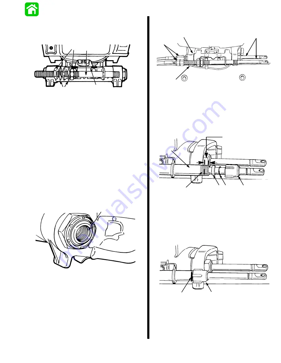
Temporarily adjust tube so that longer threaded end
of tube extends out the same distance as the out-
board tilt tube. Do not tighten adjustment nuts at this
time.
51891
a
b
c
d
a - Steering Cable Mounting Tube (End of Tube with Longer
Threads Toward Starboard Side of Boat)
b - Mounting Bracket
c - Locking Tab Washers (2)
d - Adjustment Nuts (Flats of Nuts Facing Toward Locking Tab
Washer)
Installing Steering Cables
IMPORTANT: Lubricate inside of outboard tilt
tube, inside of steering cable mounting tube and
rubber O-ring seal (located in outboard tilt tube)
with Quicksilver 2-4-C w/Teflon before installing
steering cables.
Lubricate inside of outboard tilt tube and inside of
steering cable mounting tube with Quicksilver 2-4-C
w/Teflon. Verify rubber O-ring seal (located in out-
board tilt tube) is lubricated.
51890
a
a - Seal
Insert steering cable ends thru outboard tilt tube and
cable mounting tube. Thread steering cable attaching
nuts on to tubes hand tight.
Torque steering cable attaching nuts only after final
steering adjustments have been made.
51891
a
b
c
d
a - Steering Cable Ends
b - Outboard Tilt Tube
c - Cable Mounting Tube
d - Cable Attaching Nuts
Place a mark on steering cable mounting tube 5/8 in.
(16mm) from end of mounting tube. Slide plastic
spacer, O-ring and cap over steering cable.
51890
5/8
″
(16mm)
a
b
c d
e
a - Mark
b - Steering Cable Tube
c - Spacer
d - O-ring
e - Cap
Thread cap (e) onto steering cable mounting tube, up
to mark (a).
51890
e
a
Содержание 100
Страница 4: ...GENERAL INFORMATION AND SPECIFICATIONS 1 ...
Страница 18: ...IGNITION SYSTEM ELECTRICAL AND IGNITION A 2 ...
Страница 30: ...11669 BATTERY CHARGING SYSTEM AND STARTING SYSTEM ELECTRICAL AND IGNITION B 2 ...
Страница 58: ...22480 TIMING SYNCHRONIZING ADJUSTING ELECTRICAL AND IGNITION C 2 ...
Страница 71: ...WIRING DIAGRAMS ELECTRICAL AND IGNITION D 2 ...
Страница 86: ...FUEL SYSTEM AND CARBURETION A 3 ...
Страница 118: ...OIL INJECTION SYSTEM B 3 ...
Страница 127: ...20032 3 CYLINDER ENGINES POWERHEAD A 4 ...
Страница 168: ...791 H GEAR HOUSING LOWER UNIT A 5 ...
Страница 170: ...5A 1 90 13645 2 1095 LOWER UNIT Notes ...
Страница 205: ...MID SECTION LOWER UNIT B 5 ...
Страница 207: ...5B 1 90 13645 2 495 LOWER UNIT Notes ...
Страница 218: ...SHOCK ABSORBER LOWER UNIT C 5 ...
Страница 223: ...17250 DESIGN I SIDE FILL RESERVOIR POWER TRIM A 6 ...
Страница 233: ...6A 9 POWER TRIM 90 13645 2 495 Commander Side Mount Remote Control Wiring Diagram ...
Страница 268: ...DESIGN II AFT FILL RESERVOIR POWER TRIM B 6 51344 ...
Страница 305: ...SINGLE RAM POWER TRIM C 6 51485 ...
Страница 309: ...6C 3 90 13645 2 495 POWER TRIM Notes ...
Страница 340: ...50099 ENGINE ATTACHMENTS ENGINE INSTALLATION 7 A ...
Страница 369: ...TILLER HANDLE AND CO PILOT OUTBOARD MOTOR INSTALLATION ATTACHMENTS 7 B ...
Страница 371: ...7B 1 90 13645 2 495 OUTBOARD MOTOR INSTALLATION ATTACHMENTS Notes ...