


4A-21
90-13645--2
495
POWERHEAD
3. Clean mating surfaces of crankcase cover and
intake manifold. Install new gaskets.
4. Install intake manifold/reed block assemblies to
crankcase cover. Refer to PAGE 4A-6 for torque
specification and tightening sequence.
5. Install carburetors. Torque carburetor (AIR BOX)
stud nuts to 100 lb. in. (11.3 N
m).
6. Carburetors MUST BE SYNCHRONIZED. Refer
to SECTION 2C for proper procedures.
7. Reinstall air box cover.
8. Reinstall top cowling.
Piston and Piston Rings
IMPORTANT: If engine was submerged while
engine was running, piston pin and connecting
rod may be bent. If piston pin is bent, piston must
be replaced. Piston pins are not sold separately
because of matched fit into piston. If piston pin is
bent, connecting rod must be checked for
straightness (refer to “Connecting Rods” for
checking straightness).
S
Inspect piston for scoring and excessive piston
skirt wear.
S
Check tightness of piston ring locating pins.
Locating pins must be tight.
S
Thoroughly clean pistons. Carefully remove
carbon deposits, with a soft wire brush or carbon
remover solution. DO NOT burr or round off
machined edges.
S
Inspect piston grooves for wear and carbon
accumulation. If necessary, scrape carbon from
piston ring grooves being careful not to scratch
sides of grooves. Refer to procedure for cleaning
piston ring grooves.
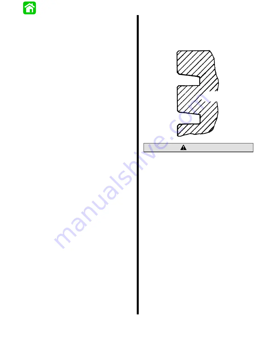
CLEANING PISTON RING GROOVES
IMPORTANT: The piston rings are half-keystone
rings – (tapered on the top side) - follow cleaning
and inspection carefully! Chromed ring is
installed on top.
Enlarged View of
Piston Ring Grooves
Care must be taken not to scratch the side
surfaces of ring groove. Scratching the side
surfaces of the ring groove will cause damage to
the ring groove.
CAUTION
Содержание 100
Страница 4: ...GENERAL INFORMATION AND SPECIFICATIONS 1 ...
Страница 18: ...IGNITION SYSTEM ELECTRICAL AND IGNITION A 2 ...
Страница 30: ...11669 BATTERY CHARGING SYSTEM AND STARTING SYSTEM ELECTRICAL AND IGNITION B 2 ...
Страница 58: ...22480 TIMING SYNCHRONIZING ADJUSTING ELECTRICAL AND IGNITION C 2 ...
Страница 71: ...WIRING DIAGRAMS ELECTRICAL AND IGNITION D 2 ...
Страница 86: ...FUEL SYSTEM AND CARBURETION A 3 ...
Страница 118: ...OIL INJECTION SYSTEM B 3 ...
Страница 127: ...20032 3 CYLINDER ENGINES POWERHEAD A 4 ...
Страница 168: ...791 H GEAR HOUSING LOWER UNIT A 5 ...
Страница 170: ...5A 1 90 13645 2 1095 LOWER UNIT Notes ...
Страница 205: ...MID SECTION LOWER UNIT B 5 ...
Страница 207: ...5B 1 90 13645 2 495 LOWER UNIT Notes ...
Страница 218: ...SHOCK ABSORBER LOWER UNIT C 5 ...
Страница 223: ...17250 DESIGN I SIDE FILL RESERVOIR POWER TRIM A 6 ...
Страница 233: ...6A 9 POWER TRIM 90 13645 2 495 Commander Side Mount Remote Control Wiring Diagram ...
Страница 268: ...DESIGN II AFT FILL RESERVOIR POWER TRIM B 6 51344 ...
Страница 305: ...SINGLE RAM POWER TRIM C 6 51485 ...
Страница 309: ...6C 3 90 13645 2 495 POWER TRIM Notes ...
Страница 340: ...50099 ENGINE ATTACHMENTS ENGINE INSTALLATION 7 A ...
Страница 369: ...TILLER HANDLE AND CO PILOT OUTBOARD MOTOR INSTALLATION ATTACHMENTS 7 B ...
Страница 371: ...7B 1 90 13645 2 495 OUTBOARD MOTOR INSTALLATION ATTACHMENTS Notes ...