


7A-4
ENGINE ATTACHMENTS
90-13645--2
495
2. Install steering cable mounting tube into mounting
bracket with 2 adjustment nuts and tab lock wash-
ers, as shown in Figure 3. Be sure that longer
threaded end of tube is toward steering cable at-
taching nut side of engine.
3. Temporarily adjust tube so that longer threaded
end of tube is extended out the same distance as
engine tilt tube. Do not tighten adjustment nuts at
this time.
16959
a
b
c
a - Steering Cable Mounting Tube
b - Tab Lock Washers
c - Adjustment Nuts (Rounded Edge Facing Out)
Figure 3. Steering Cable Mounting Tube Installed
4. Install steering cables, as follows:
IMPORTANT: Before installing steering cables, lu-
bricate inside of port mounted engine tilt tube and
inside of steering cable mounting tube with
Quicksilver 2-4-C w/Teflon. Verify that rubber O-
ring seal (located in engine tilt tube) also is lubri-
cated.
a. Lubricate inside of (port) engine tilt tube with
Quicksilver 2-4-C w/Teflon. Make sure that rub-
ber O-ring seal (located in engine tilt tube) also
is lubricated.
b. Lubricate inside of steering cable mounting
tube with Quicksilver 2-4-C w/Teflon.
c. Insert ends of steering cables thru engine tilt
tube and cable mounting tube (Figure 4).
Thread steering cable attaching nuts onto
tubes hand-tight.
a
16977
b
b
c
c
d
a - Steering Cables Routed Down Starboard Side
b - See Figure 7 for Correct Parts Sequence
c - See Figure 8 for Correct Parts Sequence
d - Seal
Figure 4. Steering Cables and Steering Link
Rods Installed
NOTE: Torque steering cables attaching nuts and
install locking sleeve after final tension adjustment.
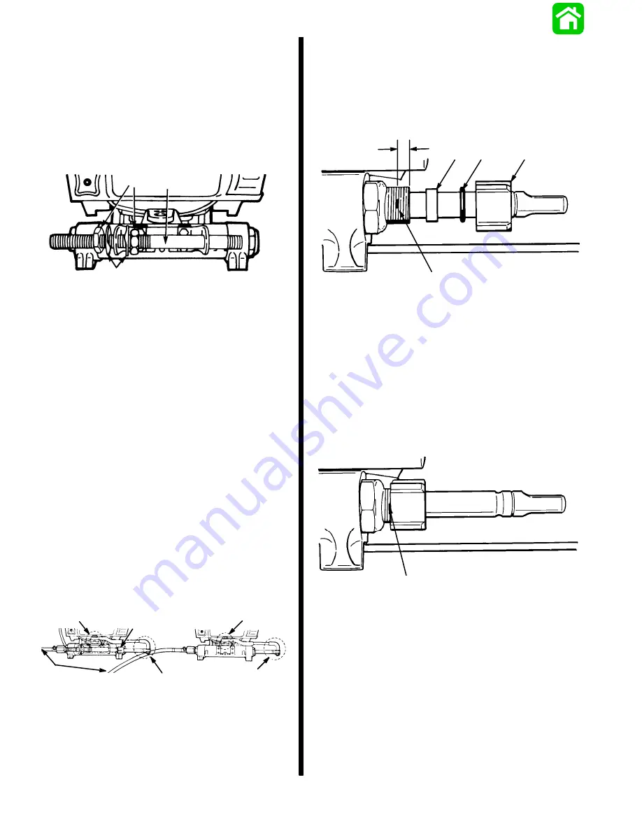
5. Install steering cable seal to steering cable
mounting tube, as follows:
a. Place a mark on steering cable mounting tube
5/8
″
(15.8mm) from end of tube (Figure 5).
50180
a
b
c
d
e
a - 5/8
″
from End of Tube
b - Place Mark on Tube Here.
c - Nylon Spacer
d - O-ring
e - Cap
Figure 5. Seal Installation Sequence
b. Slide nylon spacer, O-ring and cap (from kit)
over steering cable (Figure 5).
c. Thread cap onto steering cable mounting tube
up to mark (made on tube in Step “a” (Figure 6).
50180
a
a - Mark Made in Step 5a
Figure 6. Steering Cable Seal Installed
6. Install link rods (Figure 4) to engine steering arms.
Fasten each link rod to steering arm onto top side
rear hole with pivot bolt and locknut, as shown in
Figure 7. Torque each pivot bolt to 20 lbs. ft.
(27.1 N
m), then thread locknut onto pivot bolt
and torque nut to 20 lbs. ft. (27.1 N
m).
Содержание 100
Страница 4: ...GENERAL INFORMATION AND SPECIFICATIONS 1 ...
Страница 18: ...IGNITION SYSTEM ELECTRICAL AND IGNITION A 2 ...
Страница 30: ...11669 BATTERY CHARGING SYSTEM AND STARTING SYSTEM ELECTRICAL AND IGNITION B 2 ...
Страница 58: ...22480 TIMING SYNCHRONIZING ADJUSTING ELECTRICAL AND IGNITION C 2 ...
Страница 71: ...WIRING DIAGRAMS ELECTRICAL AND IGNITION D 2 ...
Страница 86: ...FUEL SYSTEM AND CARBURETION A 3 ...
Страница 118: ...OIL INJECTION SYSTEM B 3 ...
Страница 127: ...20032 3 CYLINDER ENGINES POWERHEAD A 4 ...
Страница 168: ...791 H GEAR HOUSING LOWER UNIT A 5 ...
Страница 170: ...5A 1 90 13645 2 1095 LOWER UNIT Notes ...
Страница 205: ...MID SECTION LOWER UNIT B 5 ...
Страница 207: ...5B 1 90 13645 2 495 LOWER UNIT Notes ...
Страница 218: ...SHOCK ABSORBER LOWER UNIT C 5 ...
Страница 223: ...17250 DESIGN I SIDE FILL RESERVOIR POWER TRIM A 6 ...
Страница 233: ...6A 9 POWER TRIM 90 13645 2 495 Commander Side Mount Remote Control Wiring Diagram ...
Страница 268: ...DESIGN II AFT FILL RESERVOIR POWER TRIM B 6 51344 ...
Страница 305: ...SINGLE RAM POWER TRIM C 6 51485 ...
Страница 309: ...6C 3 90 13645 2 495 POWER TRIM Notes ...
Страница 340: ...50099 ENGINE ATTACHMENTS ENGINE INSTALLATION 7 A ...
Страница 369: ...TILLER HANDLE AND CO PILOT OUTBOARD MOTOR INSTALLATION ATTACHMENTS 7 B ...
Страница 371: ...7B 1 90 13645 2 495 OUTBOARD MOTOR INSTALLATION ATTACHMENTS Notes ...