background image

Unpack, Inspect and Install

248083395-1 Rev 9

3-9

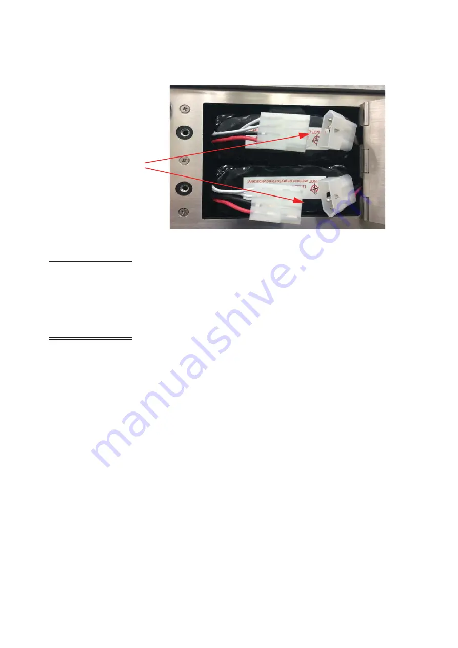
Figure 3-9  Removing Battery (Dual-Battery Units)

WARNING: 

Replace 

the instrument battery 
only with those supplied 
by Lighthouse 
Worldwide Solutions or 
the product warranty and 
CE certification will be 
voided.

Replace Battery

To replace a failed battery, follow steps 1 and 2 under “Remove the 
Batteries” on page 3-8 to remove it.  For single-battery units, follow 
steps 1 through 3 in “Install the Optional Batteries” on page 3-5 using 
Figure 3-8 to remove the original battery and Figure 3-2 through Figure 
3-4 to replace it. For dual-battery units, follow steps 4 through 6 in 
"Install the Optional Batteries" on page 3-5 using Figure 3-9 to remove 
the original batteries and Figures 3-5 and 3-6 to replace them.  Use 
caution to prevent puncturing the battery, which can cause a fire or 
explosion.  Contact Lighthouse Worldwide Solutions to get 
replacement batteries, P/N: 

403027596-1, 403028044-1, 

or

403028229-1,

 or the CE certification will be invalid.  All batteries need 

to be replaced at the same time to avoid imbalanced charging and 
shortening of battery lifespans.

Do NOT attempt to remove a battery that is swollen or too hot to 
handle.  Contact Lighthouse Worldwide Solutions support for 
assistance.  

Connect the Isokinetic Probe

The SOLAIR comes with an isokinetic sample probe, tripod stand and 
a length of sample tubing that is lined with an electrostatic reduction 
material to eliminate particle adhesion. The probe with tubing connects 
to the sample inlet.

Detach
Cables

Содержание SOLAIR 1100LD

Страница 1: ......

Страница 2: ...00...

Страница 3: ...Lighthouse Worldwide Solutions SOLAIR 1100LD Airborne Particle Counter Gen E Operating Manual...

Страница 4: ...o be disclosed such information except as permitted in writing by Lighthouse Worldwide Solutions The information contained herein is subject to change without notice Lighthouse Worldwide Solutions is...

Страница 5: ...ments for Electrical Equipment for Measurement Control and Laboratory Use Part 1 General Requirements LASER SAFETY IEN 60825 1 2014 Safety of laser products Part 1 Equipment classification and require...

Страница 6: ......

Страница 7: ...iew 2 1 Description 2 1 SOLAIR 1100LD Specifications 2 2 Chapter 3 Unpack Inspect and Install Initial Inspection 3 1 Shipping Instructions 3 1 Accessories 3 3 Installation 3 5 Install the 1100LD on Lo...

Страница 8: ...6 Additional Requirements 4 16 Configure Device 4 17 Ethernet Port Configuration 4 17 Straight through Cat5 Setup 4 17 Cross over Cat5 Setup 4 18 Program the Interface 4 18 Windows Telnet Programming...

Страница 9: ...6 26 Particle Display 6 27 Alarm 6 28 Alarm Threshold 6 28 Clear Buffer 6 30 DEVICE SETUP 6 30 Clock 6 31 Options 6 33 Contrast Adjust 6 33 Audible Beep Adjust 6 33 Align Touch Screen 6 33 Scan Mode 6...

Страница 10: ...r 7 Program the SOLAIR General Information 7 1 Instrument Communications 7 1 RJ 45 RS 485 Port 7 1 RS485 Communications 7 2 RS232 Communications 7 2 USB Communications 7 2 Using the USB Port to connec...

Страница 11: ...a Type Registers B 12 Data Units Registers B 13 Data and Alarm Registers B 14 Data and Alarm Enable Registers B 14 Enable Alarming for a Channel B 16 Threshold Setup Registers B 17 Setting the Alarm T...

Страница 12: ...Lighthouse SOLAIR 1100LD Operating Manual t vi 248083395 1 Rev 9...

Страница 13: ...could cause serious personal injury or death and damage to the instrument boldface Introduces or emphasizes a term Courier font Indicates command syntax or text displayed by the diagnostic terminal B...

Страница 14: ...Lighthouse SOLAIR 1100LD Operating Manual ii 248083395 1 Rev 9...

Страница 15: ...on This product contains a laser based sensor that is a Class 1 product as defined by FDA 21 CFR Chapter 1 Sub Chapter J when used under normal operation and maintenance Performing service on the sens...

Страница 16: ...be accompanied in this manual with a warning that 24VDC is present on connector pin 7 when instrument power is applied Port Connect Warning WARNING Connect to the SOLAIR 1 CFM instrument using the Eth...

Страница 17: ...ot or cubic meter The 1100LD uses an Extended Life laser diode light source and collection optics for particle detection Particles scatter light from the laser diode and the collection optics collect...

Страница 18: ...oncentration Cumulative Differential Real Time with LMSNet or LMS ExpressRT Data Storage Stores up to 3000 sample records in a rotating buffer particle and environmental data with location and time Ex...

Страница 19: ...tem exhaust Internally filtered to HEPA standards 100 0 1Pm Vacuum Source Internal pump automatic flow control Power 100 240 VAC 50 60Hz 300W maximum Battery Optional Li ion removable rechargeable sin...

Страница 20: ...Lighthouse SOLAIR 1100LD Operating Manual 2 4 248083395 1 Rev 9...

Страница 21: ...arton for reshipment of the instrument for its annual factory calibration Report damages to Lighthouse Technical Support at 1 800 945 5905 USA Toll Free 1 541 770 5905 Outside of USA before proceeding...

Страница 22: ...trument battery and package it to ship separately refer to www golighthouse com rma for detailed instructions Remove attachments such as TRH or Isokinetic probes and package to prevent physical and ES...

Страница 23: ...XChange software for back ups and historical data review Isokinetic Sampling Probe standard for use in unidirectional air flow to maximize correlation between counts and actual particle size distribut...

Страница 24: ...r computers that have only a USB port for communications DB 9 to RJ45 RS232 Serial Adapter optional Wireless Adapter optional LMS Express software standard an analysis tool that allows the user to 1 M...

Страница 25: ...rating requirements see SOLAIR 1100LD Specifications on page 2 2 Install the Optional Batteries If the SOLAIR 1100LD was ordered with the optional rechargeable Li ion batteries the batteries need to b...

Страница 26: ...g battery 3 Push the battery all the way into the compartment until it snaps into place as shown in Figure 3 4 Close the door and tighten the screw lock by turning it clockwise Figure 3 4 Battery Enga...

Страница 27: ...ct the SOLAIR to AC Power 1 Use the supplied region specific power cord and connect the SOLAIR to AC power The battery will start charging 2 To operate the 1100LD on AC power while charging press the...

Страница 28: ...overload which can result in fire or explosion hazard Failure to heed this warning can result in personal injury or death Remove the Batteries 1 To remove the batteries turn the power switch OFF out...

Страница 29: ...e 3 5 using Figure 3 9 to remove the original batteries and Figures 3 5 and 3 6 to replace them Use caution to prevent puncturing the battery which can cause a fire or explosion Contact Lighthouse Wor...

Страница 30: ...on top of the unit 3 Install the nut rear ferrule and front ferrule onto the tubing if needed Insert the tubing into the inlet and make sure the two ferrules contact the inlet as shown in Figure 3 11...

Страница 31: ...ed to set it up Note Thermal paper must be used The printer will not print on regular paper 1 To install new or replacement paper open the printer paper tray door by grasping each side of the printer...

Страница 32: ...4 Make sure that the paper is lined up straight with the cutting edge as shown in Figure 3 15 Figure 3 15 Aligning the Paper Note The printer door must be securely closed in order to print If the use...

Страница 33: ...etrieval It can connect to the Lighthouse Monitoring System LMS Express or RT or the LMS XChange Data Transfer Software for data download By transferring the data to the Lighthouse Monitoring System L...

Страница 34: ...Lay new fuses SloBlo 2A 250V 5x20mm into the side slots of the tray Contact Lighthouse for LWS P N 017 808915 5 Grasp the tray in a manner that holds the fuses in the tray as shown in Figure 3 17 5 P...

Страница 35: ...n the data buffer Each port can be used for one dual channel or two single channel 4 20mA sensors when wired correctly two devices total per port When each port is connected to two single channel anal...

Страница 36: ...orts are oriented with the locking tabs at the top to the left in photo Analog Setup When adding Analog Sensors to the SOLAIR s RJ12 ports the SOLAIR must be set up to accept data from the sensors The...

Страница 37: ...house TRH temperature relative humidity probe is connected to port 1 its temperature data will show up on A1 and its relative humidity data will be displayed on A2 The setup process is as follows Note...

Страница 38: ...l tag for the analog channel tag can be up to four characters 7 Press ENTER when complete 8 At the Analog Configuration Screen press the MIN value button 9 Enter the minimum value of the sensor s data...

Страница 39: ...og Units Edit Screen 13 Continue in this same way to enable the other Analog channels as desired 14 Press BACK to return to the MAIN screen 15 The Analog data can be viewed in the Zoomed Data View by...

Страница 40: ...r the report used in the user s Standard Operating Procedure Note Due to rounding of values occasionally the user may need to increase the sample volume in order to meet the requirements For each repo...

Страница 41: ...ll have an effect on the minimum locations and minimum samples required In general the Non unidirectional option requires more of both locations and samples For the Fed Std ft3 report the classificati...

Страница 42: ...s Cn m is the class limit number of particles per cubic meter for the largest considered particle size specified for the relevant class 20 is the defined number of particles that could be counted if t...

Страница 43: ...air must be shown in liters The classification for a particle size is determined based on the mean of all average concentrations taken from all locations in the cleanroom If the mean exceeds all limit...

Страница 44: ...into which it is to be installed It will list typical equipment required and provide some troubleshooting information The end of the chapter provides ARP commands to be used should the instrument get...

Страница 45: ...figuration tab and click the green arrow The Windows Security Login window will open Select OK without entering a username or password See Figure 4 7 Figure 4 7 Web Configuration Tab 3 The Device Serv...

Страница 46: ...ndicates one is needed If a gateway is needed the IT depart ment will provide one Press the OK button to save the settings Network Settings will display Done See Figure 4 9 Figure 4 9 Network Settings...

Страница 47: ...ettings Serial Settings will display Done See Figure 4 10 Figure 4 10 Serial Settings 6 Select Connections and verify that Connect Protocol and Connection settings are set to the following Protocol Mo...

Страница 48: ...Press the OK button Connections Settings will display Done as shown in Figure 4 11 Figure 4 11 Connections 7 Select Apply Settings link to save the setting to the RS485 Ethernet Adapter as shown in F...

Страница 49: ...ions on specific hosts by assigning an IP address to a MAC address ARP Cache List of IP addresses and their associated MAC addresses for hosts whose addresses cannot be resolved normally DHCP Dynamic...

Страница 50: ...Required Contact the network administrator if any of the following are not installed or not functional Windows 2000 XP Professional or Windows 7 OS Telnet Note All values in screen shots are examples...

Страница 51: ...ateway for both the PC and the SOLAIR Frequently it is necessary to change the SOLAIR 1100LD Ethernet parameters to allow for easier troubleshooting When this needed make sure the instrument is reprog...

Страница 52: ...g activity Proceed to next section Program the Interface Windows Telnet Programming 1 Start Windows 2 On the Taskbar click on Start WARNING Perform only the steps or commands as provided in this guide...

Страница 53: ...terface 8 Type arp s xxx xxx xxx xxx nn nn nn nn nn nn and press Enter Replace the x s with the desired IP address such as 192 168 0 10 or 10 10 0 15 and the n s with the desired MAC address such as 0...

Страница 54: ...m Step 9 is shown in Figure 4 18 Figure 4 18 Command Send Telnet 9999 The user will have 4 seconds to respond in the next step If they respond too slowly they will have to repeat step 10 11 Press Ente...

Страница 55: ...er See Figure 4 20 Figure 4 20 Assigning IP Address 13 Type Y to set the Gateway IP address Type the Gateway IP address and press Enter See Figure 4 21 Figure 4 21 Assigning Gateway IP Address 14 Type...

Страница 56: ...equirements If a password is applied and forgotten the instrument will have to be returned to Lighthouse to get the password cleared See Figure 4 23 Figure 4 23 Telnet Config Password Screen 16 Type S...

Страница 57: ...ached cabling Attach the network cable that will be used for production to the SOLAIR and the other end to the production network receptacle Apply power to the instrument and check the port LEDs to ve...

Страница 58: ...Lighthouse SOLAIR 1100LD Operating Manual 4 24 248083395 1 Rev 9...

Страница 59: ...ND RS485 or USB and Ethernet or all three will fail The instrument must be powered OFF before changing from one interface to another such as from USB to Ethernet The communication ports are labeled as...

Страница 60: ...it due to a DHCP change Contact the local IT or Network Administration staff for clarification and IP assignment or Lighthouse Technical Support at 800 945 5905 Toll Free USA or 541 770 5905 Outside o...

Страница 61: ...y When the cable is attached to the PC Windows will detect that a new hardware device has been attached and will finalize the installation as needed This is a routine registering of components that sh...

Страница 62: ...his is a routine registering of components that should take only a moment An additional COM port will be added to the PC 6 Identify the computer port that has been added to the PC by using the Propert...

Страница 63: ...mported and decoded in LMS Express See Figure 5 4 Note Make sure to use the supplied USB flash drive to ensure file transfer compatibility with the Solair Figure 5 4 MAIN Screen Flash Drive Attached U...

Страница 64: ...Lighthouse SOLAIR 1100LD Operating Manual 5 6 248083395 1 Rev 9...

Страница 65: ...under pressure can damage the instrument and void its warranty Sampling any gas that is not the same density as ambient air can result in inaccurate data Please contact Lighthouse at 800 945 5905 Toll...

Страница 66: ...ental conditions that are not allowed or specified in this manual or use this instrument in any manner not specified by the manufacturer may impair the protection provided by the equipment 6 Press the...

Страница 67: ...may damage the internal pump and void the warranty If the 5 Sec Startup is set default STARTING will display for five seconds when the pump turns on When the SOLAIR starts counting COUNTING appears on...

Страница 68: ...erview The SOLAIR incorporates a unique touch screen interface to control and configure the instrument This interface allows the user to easily view and configure the instrument to specific needs and...

Страница 69: ...shown in Figure 6 8 Note The screen examples in this chapter are for visual reference The values displayed may not be indicative of actual values Figure 6 8 MAIN Screen Battery Operated Figure 6 9 MAI...

Страница 70: ...screen For more details about printing see the Configuration section later in this chapter Date Time Displays the current date and time Note If the instrument is counting when the X appears in the ba...

Страница 71: ...USA for assistance or send an email to techsupport golighthouse com The mu symbol indicates the particle sizes in micrometers configured for the instrument These sizes are pre configured at the facto...

Страница 72: ...ld time the pump will restart HOLD Displays the hold time in between cycles The maximum hold time is 23 hours 59 minutes 59 seconds RECS This displays the current number of records stored in the instr...

Страница 73: ...e Locations can also be selected by touching the location name on the screen Recipes associated with a specific location may also be loaded when that location is selected The AUTO INC button when acti...

Страница 74: ...views The user can either view a single column of data differential or cumulative in a larger font or they can view both differential and cumulative data on the same screen in a smaller font Tap anyw...

Страница 75: ...gure 6 14 Zoomed Data View Buttons When the instrument is STOPPED or HOLDING the user may also press anywhere in the white data area to return to the MAIN Screen view START or STOP counting Display Pa...

Страница 76: ...ame time on the Zoomed View screen To enable this feature go to the CONFIG screen and press the Options button See Figure 6 15 Figure 6 15 CONFIG Options Button Figure 6 16 DiffCuml on Zoom Button pre...

Страница 77: ...he screen after selecting DiffCuml on Zoom are shown in Figure 6 18 Note the selections are different but their functions are the same as on dual display screen Figure 6 18 Diff Cuml Screen Button Act...

Страница 78: ...DiffCuml on Zoom button See Figure 6 19 Figure 6 19 Disable DiffCuml on Zoom press the MAIN button to return to the MAIN Screen view or press BACK to return to the previous level Here the user can ch...

Страница 79: ...cludes buttons to enable disable particle channels configure analog channels set sample record parameters sample settings thresholds enable disable alarms and clear the data buffer Device Setup includ...

Страница 80: ...abled on the Particle screen A checkmark is displayed next to each enabled channel See Figure 6 24 Figure 6 24 Particle Channel Configuration Note The data buffer is cleared when channels are enabled...

Страница 81: ...e Particle screen then selecting OK will return to the MAIN screen If the BACK button was selected then selecting OK will return to the CONFIG screen pressing CANCEL will cancel any changes and return...

Страница 82: ...a time on each port Please contact Lighthouse at 800 945 5905 Toll Free USA or 541 770 5905 Outside of USA for additional information about converters and wiring Figure 6 26 Analog Port Connectors An...

Страница 83: ...e top row second column to enter TYPE data The example shown in Figure 6 28 illustrates entering a temperature probe type Examples of types would be TEMP RH AIRV or AV and DP Keep in mind that the typ...

Страница 84: ...er at a time and the ENTER to accept the value The BACK button will return to the previous screen without making any changes Figure 6 29 Analog Units Screen Touching the MIN or MAX column button activ...

Страница 85: ...o review the settings To return any of the screens to correct or change an entry requires only to press the corresponding button Figure 6 31 Analog Settings Complete Screen Analog Data Display Figure...

Страница 86: ...ta display area to activate the Zoomed Data View Touch the Particle button to switch view to analog data See Figure 6 33 Figure 6 33 Zoomed Analog Data Displayed Sample The Sample screen allows the us...

Страница 87: ...econds using the numeric keypad on the right After the value is entered press ENTER Note If the Hold time is set to 00 00 00 in Auto Mode the instrument will run the samples according to the sample ti...

Страница 88: ...ume in cubic feet ft3 cubic meters m3 or liters l When this is set the corresponding Sample Volume will automatically be set See Figure 6 35 Figure 6 35 Changing Sample Volume Unit of Measure Note If...

Страница 89: ...0 the instrument will continue indefinitely in Auto Mode until the STOP button is pressed MANU Manual Mode When the instrument is in Manual Mode it will start counting when START is pressed and stop a...

Страница 90: ...of the channels enabled for alarming Note If BEEP mode is set to one count each beep may not be for every single count The data will be recorded based on the set sample time and hold time and can be...

Страница 91: ...s between 1Pm and 2 5Pm The data displays on the MAIN screen according to whichever is selected DIFF or CUML The data format is either Raw RAW or Normalized NORM Raw data displays the actual number of...

Страница 92: ...al data the alarm threshold will apply to the differential counts If the instrument is set to display Cumulative data the alarm threshold will apply to the cumulative counts To enable the alarming for...

Страница 93: ...splay a selection cursor as shown in Figure 6 39 Note Alarms are triggered per sample record At the end of the sample time the alarm is reset Figure 6 39 MAIN screen Enabled for Alarming When a partic...

Страница 94: ...ins Clear Buffer To clear the data buffer on the instrument press the Clear Buffer button See Figure 6 41 Figure 6 41 Clear Buffer Screen Press OK to clear the data or press Cancel to exit screen with...

Страница 95: ...entering values for the desired month day and year and then press the ENTER button Note MONTH 1ST M D Y is the default date format Change the Date s format by pressing the M D Y button to display the...

Страница 96: ...ear First Set the instrument s Time by pressing the TIME button See Figure 6 46 Figure 6 46 Configuring TIME Enter the desired Time in hours minutes and seconds then press ENTER to save the new time P...

Страница 97: ...Screen Contrast Adjust The contrast brightness of the LCD screen can be adjusted by pressing the first set of UP and DOWN arrows Audible Beep Adjust The audio level of the BEEP can be adjusted by pres...

Страница 98: ...igure 6 48 Alignment Screen 1 Note Using a PDA Stylus provides higher accuracy to the touch screen interface At the next screen touch the arrow displayed in the upper right corner This needs to be don...

Страница 99: ...e to be touched three times to ensure calibration as Figure 6 50 illustrates this Figure 6 50 Alignment Screen 3 The fourth alignment screen shown in Figure 6 51 displays the arrow in the at the botto...

Страница 100: ...n alignment function can also be accessed by touching the screen when powering the instrument on Once the final alignment is complete the following screen is displayed See Figure 6 52 Touch anywhere i...

Страница 101: ...M particle counters using the ScanAir or ScanAir Pro Filter Scanners Figure 6 53 Scan Mode Button When using the ScanAir or ScanAir Pro Filter Scanners in conjunction with 1 CFM particle counters the...

Страница 102: ...on Zoom If DiffCuml on Zoom is enabled the counter s display will show two columns of data simultaneously Differential and Cumulative One Channel If One Channel is enabled only the first channel will...

Страница 103: ...ime MODBUS Output mode will be automatically disabled Hold Time Zero seconds Cumulative Differential Cumulative CUML Raw Normalized Raw When counting the MAIN Screen will update continuously and data...

Страница 104: ...95 1 Rev 9 Language Pressing the LANGUAGE button allows the user to change the operating language displaying the screen shown in Figure 6 56 Figure 6 56 Operating Language Screen Press the desired lan...

Страница 105: ...ll search for the instrument by the COMM Address specified on the Communication screen shown below COMM addresses range from 1 to 63 For RS485 communications each device on a multi port chain must hav...

Страница 106: ...gure 6 58 illustrates the USB options Figure 6 58 Output Setup Screen USB Settings Each Dataxxxx csv file is managed separately and data is added to the file while the flash drive is attached When the...

Страница 107: ...t allows the data from an LSD file to be imported into LMS Express See Figure 6 59 Figure 6 59 LMS Express LSD File Import If a USB Flash Drive is attached to the SOLAIR the PRINTER icon will change t...

Страница 108: ...condition Print Reverse This option reverses the direction that the printouts of single records come out of the instrument By default Print Reverse is disabled Since all reports calculate the data in...

Страница 109: ...ppear on the printouts Print Reverse This option reverses the direction that the printouts of single records come out of the instrument By default Print Reverse is disabled See Figure 6 63 Figure 6 63...

Страница 110: ...e ACTION Redirect output to printer Figure 6 64 Door is Closed and Latched The printer paper may be loaded backwards ACTION open the printer door and verify that the paper is feeding from the TOP of t...

Страница 111: ...t might get off center if the printouts are torn off too quickly ACTION put in a new roll of thermal paper Security Use the Security screen to restrict access to the instrument and or instrument confi...

Страница 112: ...e the last character if needed Press the ENTER button to save and return to the previous screen See Figure 6 68 WARNING Be sure to record the unit s passwords in a safe place If the password is lost o...

Страница 113: ...ng the numeric keypad Press the ERASE button to delete the last character if needed Press ENTER to save the changes and return to the Security screen Figure 6 69 CONFIGURATION Password Access Screen S...

Страница 114: ...instrument program versions of the various firmware modules This information is useful when contacting Lighthouse Technical Support personnel See Figure 6 70 Figure 6 70 SOLAIR 1100LD STATUS Screen Re...

Страница 115: ...up to 12 characters Note If the location selected is already assigned to another recipe or if there are no available free locations the user will not be able to add a new recipe The Add button will n...

Страница 116: ...the recipe settings The LOAD and UNLOAD buttons add or remove the highlighted recipe as the instrument s current operating configuration The DELETE button will delete any highlighted recipes from the...

Страница 117: ...ocations and associated alphanumeric labels Press the LOC button on the Configuration screen to display the Select Location screen as shown in Figure 6 76 Figure 6 76 LOCATION Setup Screen On the Sele...

Страница 118: ...th a specific location are denoted by an asterisk to the right of the location name When selecting a location with a recipe the user is provided with the option of loading the recipe as shown in Figur...

Страница 119: ...o to the next location to be edited and press the EDIT button Continue in the same way to edit as many Locations as desired Press the BACK button to return to the Configuration screen or the MAIN butt...

Страница 120: ...79 Auto Increment Prompt The Auto Increment mode will select the next corresponding location and continue to sample using the current configuration If the current location is using a recipe the user...

Страница 121: ...be the most current record and not the first record stored In this case older data will be lost if it hasn t been printed or transferred to a PC or management system Particle concentration data displa...

Страница 122: ...pped and older data is being overwritten The basic concept is First In First Out FIFO Size Lists the channel sizes configured on the instrument Diff Diff ft3 Diff m3 Indicates that each channel size s...

Страница 123: ...arms If the data record exceeded alarm thresholds printouts show Alarm Yes Laser Indicates the status of the laser at the time the data record was recorded possible laser states include OK or SRVC If...

Страница 124: ...Differential Data Particles m3 Normalized Counts Cumulative Data Particles ft3 Normalized Counts Cumulative Data Particles m3 The following sections describe printing options available from the Data V...

Страница 125: ...printing the report Note Printing ALL records may take some time if the buffer is full If the entire buffer is to be printed press ALL to print all of the stored records Print Range Buffer Report The...

Страница 126: ...Normalized Counts Cumulative Data Particles ft3 Normalized Counts Cumulative Data Particles m3 Printing Buffer Report To print a range of data from the buffer scroll to the first data SOLAIR 1100LD Se...

Страница 127: ...ange screen will display as shown in Figure 6 84 Figure 6 84 Print Range Screen Buffer Enter the number of records to print and press the ENTER button Note Printing ALL records may take some time if t...

Страница 128: ...58 5 0 20 507 0 0 30 145 0 0 50 15 5 1 00 5 0 Size Avg 0 10 7408 0 Size 95 UCL 0 10 13659 7 0 15 7283 9 0 20 2764 7 0 30 788 0 0 50 34 5 1 00 15 2 SUMMARY SOLAIR 1100 Serial 130705002 Location LOC001...

Страница 129: ...re taken In this case add one or two seconds to the sample time so that the user is not at the exact minimum volume Enable the Reports feature by pressing the red X Default position located at the top...

Страница 130: ...screen the number of samples taken for the report If Auto Increment is enabled the user will be prompted to move the particle counter to the next assigned location after the completed number of cycles...

Страница 131: ...samples and volume per channel in order to classify a cleanroom with that standard Use these displayed minimum values to configure the instrument so that the minimum requirements needed to classify t...

Страница 132: ...ghted in blue Class Levels vary based on which standard has been selected in the PRINT REPORT field Below are the available Class Levels per standard FED_209E ft3 1 10 100 1000 10000 100000 ISO14644 1...

Страница 133: ...The maximum area that can be entered depends on the number of locations available on the unit With all 200 locations available the Max area that can be entered is limited to a 5 digit value for ft2 an...

Страница 134: ...Choose the appropriate type of air flow Unidirectional Non Unidirectional then press the BACK button to return to the SETUP screen The SETUP screen shown in Figure 6 94 will display the values that we...

Страница 135: ...sable particle channels as shown in Figure 6 95 Figure 6 95 Reports Particle Screen Press the BACK button Press the SAMPLE button to configure the number of Cycles Delay time Hold time Sample time and...

Страница 136: ...orts Settings Screen Press the BACK button Press the LOC button to select add or delete locations or enable Auto Inc as shown in Figure 6 98 Note If the location is already assigned to another recipe...

Страница 137: ...Figure 6 99 Figure 6 99 Reports Setup Screen When REPORTS are enabled the LOC and SAVE buttons are displayed only when there are at least the minimum number of locations needed for the recipe are ava...

Страница 138: ...air flow operational room status This will generate the following minimum requirements Note The Minimum Volumes are measured in the standard measurement required by each specific report The number of...

Страница 139: ...n Press the Location Select button at the top of the screen Press the location where the first measurement will be taken Press START Let the instrument record 1 sample at the first location After the...

Страница 140: ...the CANCEL button Report Requirements Fed Std ft3 This report requires a minimum of 2 locations be measured at least 1 sample be taken per location and at least 5 samples total be taken in each cleanr...

Страница 141: ...he 0 5 and 5 0 micron channel sizes EU GMP 2009 The EU GMP Standard Report requires that the unit has the channel sizes 0 5P and 5 0P as these are the only channels that apply to this standard The EU...

Страница 142: ...andard ft3 report Federal Standard Ft 3 SOLAIR 1100LD Serial 130705002 Targeted Class 10000 Room Area 10ft 2 Room Stat Operational Air Flow Unidirect Min Loc 2 Min Samples Room 5 Recipe FED_TEST 07 10...

Страница 143: ...ational Air Flow Unidirect Min Loc 2 Min Samples Room 2 Recipe ISO_TEST 07 10 2013 15 10 17 Particle Size 0 50 Cumulative p m 3 Vol Req 2 000 L Concen Limit 3520000 Loc Samples AvgConcen LOC001 2 671...

Страница 144: ...00 m 2 Room Stat Operational Air Flow Unidirect Min Loc 3 Min Samples Room 3 Recipe EU_GMP_TEST 07 10 2013 16 12 09 Particle Size 0 5 Cumulative p m 3 Vol Req 2 000 L Concen Limit 3520000 Loc Samples...

Страница 145: ...el and before the battery reaches its critical low point the instrument will shut down all power To prevent loss of power attach the AC cord and plug into an outlet as soon as the BATT LOW message app...

Страница 146: ...Operate SOLAIR 248083395 1 Rev 9 6 82...

Страница 147: ...he basic configuration for the instrument to meet some specific needs Instrument Communications RJ 45 RS 485 Port WARNING 24VDC is present on RS 232 485 IN port pin 7 when instrument power is applied...

Страница 148: ...perform as expected A standard Cat5 cable is used to connect the instrument to an RS485 network Table 7 1 illustrates the RS232 RS485 RJ45 pins and the signals assigned RS232 Communications The instr...

Страница 149: ...re the driver has been installed will be problematic Refer to the following Note Make sure the USB driver has been installed on the PC before connecting and applying power to the instrument 1 Remove p...

Страница 150: ...from it Use the port assignment determined above Configuring with the MODBUS Protocol When powering up the instrument the pump will automatically turn on after 3 seconds and it will begin sampling us...

Страница 151: ...of the REMOTE counter are Location Sample Time Hold Time and Initial Delay The Location is set by writing an unsigned integer to register 40026 The range of values is from 0 to 999 Sample Time Hold Ti...

Страница 152: ...l Delay high Works in conjunction with 40030 Number of seconds to wait before starting the first sample Max value is 86 399 which equals 23h 59m 59s 40030 unsigned integer Initial Delay low 40031 unsi...

Страница 153: ...on 5 Enable Remote Control Locks out the instrument s user interface Can only change instrument parameters via MODBUS 6 Enable Local Control Unlocks the instrument s user interface Instrument changes...

Страница 154: ...me is effectively the time between a STOP and a START command After the last desired sample is taken send the following to stop the pump 8 Stop Pump AUTOMATIC Counting Mode In Automatic counting mode...

Страница 155: ...1 before starting Review Safety Considerations on page 1 1 and Installation on page 3 5 before replacing the battery or power cord Safety Before performing any of the maintenance tasks described in t...

Страница 156: ...repeat the test 9 After the instrument has met the requirement of the Purge Count test return the instrument to its normal location and operating status Troubleshooting If the instrument fails the Pu...

Страница 157: ...PARTICLE CHANNELS ALL CH ENABLED OF CYCLES 10 DELAY TIME 00 00 04 HOLD TIME 00 00 10 SAMPLE TIME 00 01 00 SAMPLE VOLUME FT3 COUNT MODE AUTO PARTICLE DISPLAY CUML DATA FORMAT RAW PARTICLE VOL FT3 PART...

Страница 158: ...Lighthouse SOLAIR 1100LD Operating Manual A 2 248083395 1 Rev 9...

Страница 159: ...upported MODBUS Commands See www modbus org for documentation on how to use these commands Table B 1 MODBUS Communications Settings Baud Rate 19200 Data Bits 8 Stop Bits 1 Parity None Hardware Protoco...

Страница 160: ...us bit 0 RUNNING bit 1 SAMPLING bit 2 NEW DATA bit 3 DEVICE ERROR 40004 unsigned integer Firmware version Major version digits are hundreds Minor version digits are tens and ones For example 210 v2 10...

Страница 161: ...for the Universal Manifold and values 1 6 for the MiniManifold Controller moves the arm to that position on the manifold Value 0 moves arm to Home position 40027 unsigned integer Real Time Clock RTC h...

Страница 162: ...integer Calibration Reference Voltage millivolts 40049 signed integer Printer Options 40050 signed integer Device Options Bit 3 Number of Locations 1 400 locations with four character names 0 200 loc...

Страница 163: ...print the last recorded data at the end of each sample This feature cannot be enabled if the One Second Data Update feature is enabled 40997 ASCII string Location_200_char 2 char 3 40998 ASCII string...

Страница 164: ...d with location index values For example the name for location 3 would be located at registers 40204 40205 If Bit 3 of Register 40050 is 0 up to 200 locations can be specified Registers 40200 40999 ar...

Страница 165: ...is actually sampling data that is to be recorded Caution must be used in sending a command during this time that may invalidate current sample 2 NEW DATA Set to 1 to indicate that a new data record ha...

Страница 166: ...t executes samples and holds until an Instrument Stop command is issued For instruments with pumps this command will start the pump Manifold Controller Uses defined Manifold Sequence Stops counting an...

Страница 167: ...active Retrieving data from an inactive channel returns garbage See the Data Enable Registers section of this document for details on how to record data from active channels This entire series of regi...

Страница 168: ...unsigned integer Particle Channel 2 low 30013 unsigned integer Particle Channel 3 high 30014 unsigned integer Particle Channel 3 low 30015 unsigned integer Particle Channel 4 high 30016 unsigned inte...

Страница 169: ...er For example a Flow Alert and a Particle Overflow would return a value of 6 in register 30008 bits 1 and 2 are set TRUE Bits 7 to 31 are currently unused Valid Data in Channels 30074 Register 30074...

Страница 170: ...the 30xxx series The Data Type registers run in parallel with the Data Registers For example Data Register 30041 s Data Type register is 41041 Data Types are assigned 4 ASCII characters across 2 regis...

Страница 171: ...are stored as 4 character ASCII strings across 2 registers If the Units string contains less than 4 characters or no characters at all the rest of the string is padded with NULLs The table below show...

Страница 172: ...ARM ENABLE These registers supersede the older Data Enable Registers 31xxx which have been obsoleted m Meters Bar Bar ft 2 Square feet mBar Milli bar m 2 Square meters V Volts ft 3 Cubic feet mV Milli...

Страница 173: ...int Enable for Particle Channel 2 high 43012 unsigned int Enable for Particle Channel 2 low 43013 unsigned int Enable for Particle Channel 3 high 43014 unsigned int Enable for Particle Channel 3 low 4...

Страница 174: ...channels are enabled for alarms Use the Threshold registers to set the alarm threshold value This is described in the next section 43045 unsigned int Enable for Analog Channel 3 high 43046 unsigned in...

Страница 175: ...un in parallel with the data registers 30xxx series For example data register 30010 s corresponding threshold register would be 45010 Data register 30016 s threshold register would be 45016 Table B 16...

Страница 176: ...Particle Channel 8 high 45024 unsigned int Threshold for Particle Channel 8 low Table B 17 Alarm Threshold Registers set to default value Registers Particle Channel Threshold Value 45009 45010 1 1000...

Страница 177: ...oftware tool Procedure for Computer USB port to SOLAIR only Note Data obtained from a SOLAIR directly through MODBUS is real time and has not been stored on the SOLAIR Data format is little endian ref...

Страница 178: ...1 Flow rate 1 0 CFM displays 9 Flow rate 1 0 CFM displays 1 1 8 For laser values read registers 30069 and 30070 as Float32 Laser value is displayed as a percentage of the value set during calibration...

Страница 179: ...nties and remedies granted under this Section may at LWS s option be terminated C THE FOREGOING WARRANTY IS EXCLUSIVE AND IN LIEU OF ALL OTHER REPRESENTATIONS WARRANTIES AND COVENANTS EXPRESS OR IMPLI...

Страница 180: ...Lighthouse SOLAIR 1100LD Operating Manual D 2 248083395 1 Rev 9...

Страница 181: ...12 Alarm Registers Enable Alarming B 16 Alarm Setup 6 28 Alarm Status 6 59 Alarm Threshold 6 28 Alarms Acknowledge 6 6 Align Touch Screen 6 33 Analog Channels 6 18 Analog Sensors 4 1 Analog Setup 4 2...

Страница 182: ...49 Configuration Password 6 49 Configuration Screen 6 15 Data Setup 6 15 Device Setup 6 15 Configuring with the MODBUS Protocol 7 4 Connecting Isokinetic Probe 3 9 Connecting Power 3 7 Connecting to E...

Страница 183: ...the 1100LD 3 5 Installing the Battery 3 5 Instrument Control 7 7 Instrument Start 7 7 IP 4 19 IP Address 4 15 IP address 4 16 ISO 14644 1 6 65 ISO 14644 1 4 8 Isokinetic probe Accessories 3 3 K Key S...

Страница 184: ...4 6 45 Print Separator 6 44 Print Serial Number 6 44 P Paper Thermal 3 10 Particle Channels 6 16 Particle Display 6 27 Particle Scanner Diluter 3 3 PC Ethernet port 5 2 Peripheral Interface Connector...

Страница 185: ...25 Sample Time 6 8 6 23 Sample Timing 6 22 Sample Volume 6 24 Save 7 7 Save Last Record to Flash Drive 6 6 SCAN MODE button 6 6 ScanAir Filter Scanning Probe 3 3 ScanAir Pro Filter Scanning Probe 3 3...

Страница 186: ...llation notes 5 3 7 3 USB Flash Drive 5 5 USB port assignment 5 4 7 4 Use 3 7 Using the Counter First Use 6 1 V Vacuum Source 2 3 Valid Data B 11 Validation Documentation Accessories 3 4 View Buffer A...

Страница 187: ...00...

Страница 188: ......

Отзывы: