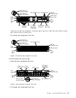
management network provides additional security by physically separating the management network
traffic from the production network. You can use the Setup Utility to configure the server to use a
dedicated systems management network or a shared network. See Using the Setup Utility in the
Problem
Determination and Service Guide
for more information.
•
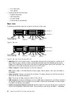
Ethernet connectors:
Use either of these connectors to connect the server to a network. When you
enable shared Ethernet for IMM2.1 in the Setup Utility, you can access the IMM2.1 using either the
Ethernet 1 or the system-management Ethernet (default) connector. See Using the Setup Utility for
more information.
•
Serial connector (optional):
Connect a 9-pin serial device to this connector. The serial port is shared
with the IMM2.1. The IMM2.1 can take control of the shared serial port to redirect serial traffic, using
Serial over LAN (SOL).
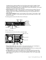
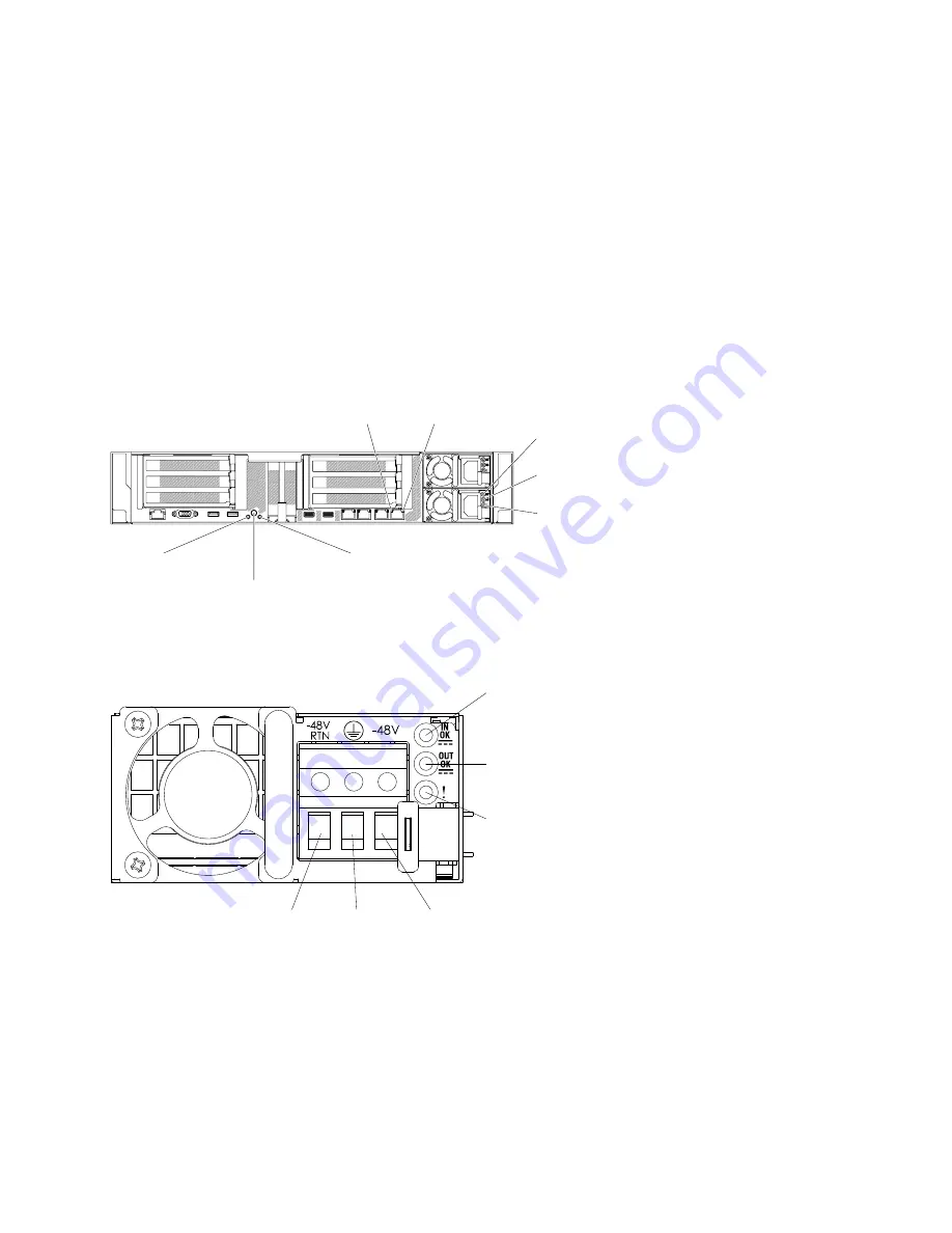
The following illustration shows the LEDs on the rear of the server.
000000
000000
000000
000000
000000
000000
00
00
00
00
00
00
00
0
0
0
0
0
0
0
0
00
00
00
00
00
00
0000000
0000000
0000000
0000000
0000000
0000000
Ethernet
link LED
Ethernet
activity LED
AC power
LED (green)
DC power
LED (green)
Power-supply
error LED (yellow)
System power LED
System error LED
Locator batton / LED
000000
000000
000000
Figure 24. LEDs rear view
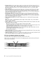
The following illustration shows the LEDs on a dc power supply.
Power input LED
Power output LED
Power error LED
-48V
Ground
-48V return
•
Ethernet activity LEDs:
When these LEDs are lit, they indicate that the server is transmitting to or
receiving signals from the Ethernet LAN that is connected to the Ethernet port.
•
Ethernet link LEDs:
When these LEDs are lit, they indicate that there is an active link connection on the
10BASE-T, 100BASE-TX, or 1000BASE-TX interface for the Ethernet port.
•
AC power LED:
Each hot-swap ac power supply has an ac power LED. When the ac power LED is
lit, it indicates that sufficient power is coming into the power supply through the power cord. During
typical operation, the ac power LED is lit. For any other combination of LEDs, see “AC power-supply
LEDs” on page 75.
25
Содержание x3650 M5
Страница 1: ...Lenovo System x3650 M5 Installation and Service Guide Machine Type 8871 ...
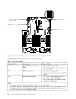
Страница 47: ...Figure 35 System board switches jumpers and buttons Chapter 1 The System x3650 M5 server 35 ...
Страница 60: ...48 Lenovo System x3650 M5 Installation and Service Guide ...
Страница 80: ...68 Lenovo System x3650 M5 Installation and Service Guide ...
Страница 124: ...112 Lenovo System x3650 M5 Installation and Service Guide ...
Страница 146: ...134 Lenovo System x3650 M5 Installation and Service Guide ...
Страница 1322: ...1310 Lenovo System x3650 M5 Installation and Service Guide ...
Страница 1329: ...People s Republic of China Class A electronic emission statement Taiwan Class A compliance statement Appendix E Notices 1317 ...
Страница 1330: ...Taiwan BSMI RoHS declaration 1318 Lenovo System x3650 M5 Installation and Service Guide ...
Страница 1339: ......
Страница 1340: ......

