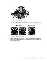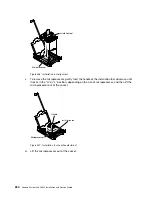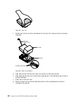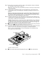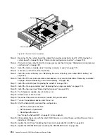
Figure 259. Heat sink
c.
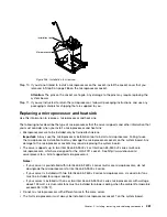
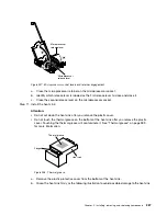
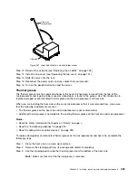
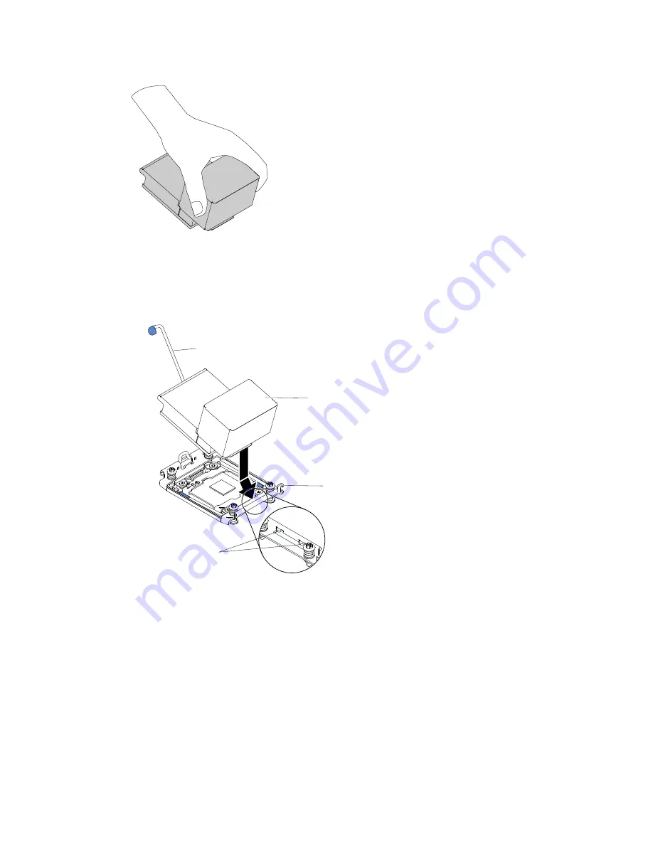
Position the heat sink over the microprocessor. The heat sink is keyed to assist with proper
alignment.
Retainer bracket tabs
Heat sink
release lever
Lock tab
Heat sink
Figure 260. Heat sink installation
d.
Align and insert the front tab of the heat sink under the retainer bracket tabs.
e.
Align and place the heat sink on top of the microprocessor in the retention bracket, thermal
material side down.
f.
Press firmly on the heat sink.
g.
Rotate the heat sink retention module release lever to the closed position and hook it
underneath the lock tab.
288
Lenovo System x3650 M5 Installation and Service Guide
Содержание x3650 M5
Страница 1: ...Lenovo System x3650 M5 Installation and Service Guide Machine Type 8871 ...
Страница 47: ...Figure 35 System board switches jumpers and buttons Chapter 1 The System x3650 M5 server 35 ...
Страница 60: ...48 Lenovo System x3650 M5 Installation and Service Guide ...
Страница 80: ...68 Lenovo System x3650 M5 Installation and Service Guide ...
Страница 124: ...112 Lenovo System x3650 M5 Installation and Service Guide ...
Страница 146: ...134 Lenovo System x3650 M5 Installation and Service Guide ...
Страница 1322: ...1310 Lenovo System x3650 M5 Installation and Service Guide ...
Страница 1329: ...People s Republic of China Class A electronic emission statement Taiwan Class A compliance statement Appendix E Notices 1317 ...
Страница 1330: ...Taiwan BSMI RoHS declaration 1318 Lenovo System x3650 M5 Installation and Service Guide ...
Страница 1339: ......
Страница 1340: ......

