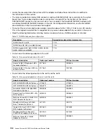
Table 19. Non-supported adapters in the slot 3 and the slot 8 (continued)
Adapter description
Option part number
FRU part number
Intel x520 Dual Port 10GbE SFP+
Adapter for System x
49Y7960
49Y7962
Emulex VFA5 2x10GbE SFP+
Adapter for System x
00JY830
00JY833
• Any high-definition video-out connector or stereo connector on any add-on video adapter is not
supported.
• When you install any PCI adapter, the power cords must be disconnected from the power source before
you remove the PCI Express riser-card assembly. Otherwise, the active power management event signal
will be disabled by the system-board logic, and the Wake on LAN feature might not work. However, after
the server is powered-on locally, the active power manager active power management event signal will
be enabled by the system-board logic.
• When you install an Intel X540 ML2 Dual Port 10GbaseT Adapter (Option part number is 00D1994),
you need to install the PCIe Thermal Solution Kit (Option part number: 00MU908) first to avoid the
potential thermal issue.
• Support Intel MIC GPU cards (3120A and 7120A) up to 35C/3000ft, otherwise GPU card performance
could be downgraded.
Attention:
1. Do not install over 3 ServeRAID M1215 SAS/SATA controllers in one system.
2. Do not install the NVIDIA Grid Kx/Mxx, the NVIDIA Quadro Kxxxx or the NVIDIA Tesla Kxx adapter
options in systems containing 1 TB of system memory or more. If these options are installed in systems
with 1 TB of memory or more, it might cause undetected data corruption and system instability. These
options are only supported in systems containing less than 1 TB of memory. For more information, go to
https://support.lenovo.com/us/en/documents/migr-5096047.
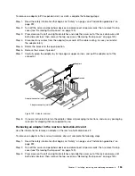
To replace an adapter, complete the following steps:
Step 1.
Read the safety information that begins on “Safety” on page v and “Installation guidelines” on
page 297.
Step 2.
Turn off the server and peripheral devices and disconnect the power cords and all external cables.
Step 3.
Remove the server top cover (see “Removing the top cover” on page 149).
Step 4.
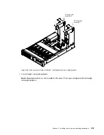
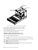
Determine which expansion slot you will use for the adapter. If you are installing an adapter in PCI
expansion slot 1, 2, or 3, remove riser-card assembly 1; if you are installing an adapter in expansion
slot 6, 7, or 8, remove riser-card assembly 2. See “Removing a riser-card assembly” on page 186
Step 5.
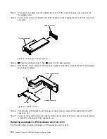
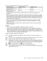
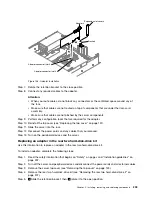
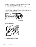
1
Slide the retention bracket; then,
2
rotate it to the open position.
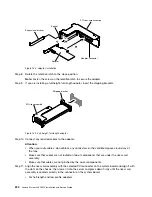
Step 6.
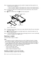
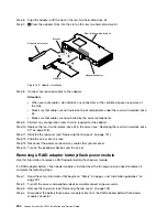
Slide the expansion-slot cover out of the riser-card assembly expansion slot.
Step 7.
Align the adapter with the PCI connector on the riser card and press the adapter firmly into the PCI
connector on the riser card.
Installing, removing, and replacing components
199
Содержание x3650 M5
Страница 1: ...Lenovo System x3650 M5 Installation and Service Guide Machine Type 8871 ...
Страница 47: ...Figure 35 System board switches jumpers and buttons Chapter 1 The System x3650 M5 server 35 ...
Страница 60: ...48 Lenovo System x3650 M5 Installation and Service Guide ...
Страница 80: ...68 Lenovo System x3650 M5 Installation and Service Guide ...
Страница 124: ...112 Lenovo System x3650 M5 Installation and Service Guide ...
Страница 146: ...134 Lenovo System x3650 M5 Installation and Service Guide ...
Страница 1322: ...1310 Lenovo System x3650 M5 Installation and Service Guide ...
Страница 1329: ...People s Republic of China Class A electronic emission statement Taiwan Class A compliance statement Appendix E Notices 1317 ...
Страница 1330: ...Taiwan BSMI RoHS declaration 1318 Lenovo System x3650 M5 Installation and Service Guide ...
Страница 1339: ......
Страница 1340: ......

