00
00
00
00
00
0
0
0
0
0
0
0000
0000
0000
0000
0000
0000
0000
0000
0000
0000
0
0
0
0
00
00
00
00
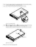
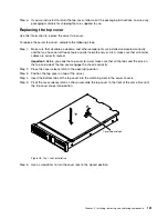
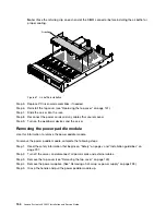
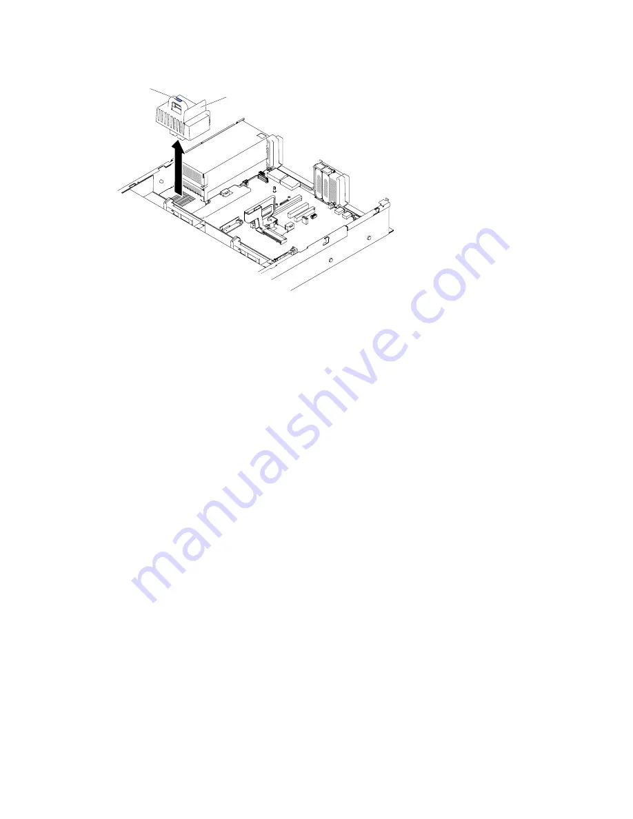
Power paddle assembly
Handle
Figure 82. Power paddle module removal
Step 6.
If you are instructed to return the power paddle module, follow all packaging instructions, and use
any packaging materials for shipping that are supplied to you.
Replacing the power paddle module
Use this information to install the power paddle module.
To install the power paddle module, complete the following steps:
Step 1.
Read the safety information that begins on “Safety” on page v and “Installation guidelines” on
page 297.
Step 2.
Turn off the server and peripheral devices and disconnect the power cords and all external cables,
if necessary.
Step 3.
Remove the top cover (see “Removing the top cover” on page 149).
Step 4.
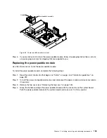
Grasp the handle and align the power paddle module with the connector on the system board.
Push the power paddle module to the system board and make sure it is firmly seated.
Installing, removing, and replacing components
155
Содержание x3650 M5
Страница 1: ...Lenovo System x3650 M5 Installation and Service Guide Machine Type 8871 ...
Страница 47: ...Figure 35 System board switches jumpers and buttons Chapter 1 The System x3650 M5 server 35 ...
Страница 60: ...48 Lenovo System x3650 M5 Installation and Service Guide ...
Страница 80: ...68 Lenovo System x3650 M5 Installation and Service Guide ...
Страница 124: ...112 Lenovo System x3650 M5 Installation and Service Guide ...
Страница 146: ...134 Lenovo System x3650 M5 Installation and Service Guide ...
Страница 1322: ...1310 Lenovo System x3650 M5 Installation and Service Guide ...
Страница 1329: ...People s Republic of China Class A electronic emission statement Taiwan Class A compliance statement Appendix E Notices 1317 ...
Страница 1330: ...Taiwan BSMI RoHS declaration 1318 Lenovo System x3650 M5 Installation and Service Guide ...
Страница 1339: ......
Страница 1340: ......


