00000000000000000
00000000000000000
00000000000000000
00000000000000000
00000000000000000
00000000000000000
00000000000000000
00000000000000000
00000000000000000
00000000000000000
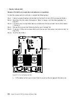
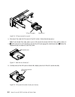
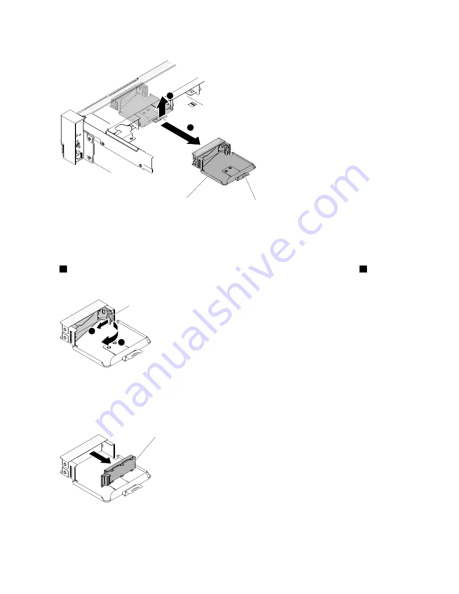
LCD panel assembly
Release latch
2
1
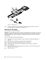
Figure 216. LCD panel assembly removal
6. Disconnect the cable from the back of the LCD system information display panel.
Note:
To disconnect the cable, press evenly on the connector release latch first; then, pull the cable out.
7.
1
Pull the tab on the LCD retention bracket to the left to disengage the retention bracket.
2
Rotate the
retention bracket to remove it from the server.
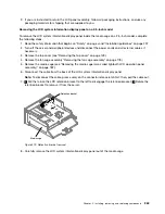
Retention bracket
2
1
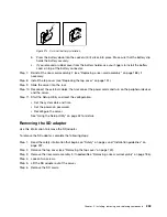
Figure 217. Retention bracket removal
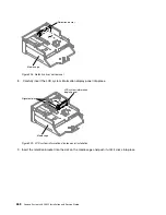
8. Carefully remove the LCD system information display panel out of the LCD panel assembly.
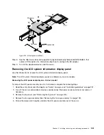
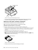
LCD system information
display panel
Figure 218. LCD system information display panel removal
262
Lenovo System x3650 M5 Installation and Service Guide
Содержание x3650 M5
Страница 1: ...Lenovo System x3650 M5 Installation and Service Guide Machine Type 8871 ...
Страница 47: ...Figure 35 System board switches jumpers and buttons Chapter 1 The System x3650 M5 server 35 ...
Страница 60: ...48 Lenovo System x3650 M5 Installation and Service Guide ...
Страница 80: ...68 Lenovo System x3650 M5 Installation and Service Guide ...
Страница 124: ...112 Lenovo System x3650 M5 Installation and Service Guide ...
Страница 146: ...134 Lenovo System x3650 M5 Installation and Service Guide ...
Страница 1322: ...1310 Lenovo System x3650 M5 Installation and Service Guide ...
Страница 1329: ...People s Republic of China Class A electronic emission statement Taiwan Class A compliance statement Appendix E Notices 1317 ...
Страница 1330: ...Taiwan BSMI RoHS declaration 1318 Lenovo System x3650 M5 Installation and Service Guide ...
Страница 1339: ......
Страница 1340: ......

