Chapter 5. Installing, removing, and replacing components
Use this information to install, remove, and replace the server components.
Replaceable components consist of the following:
•
Structural parts:
Purchase and replacement of structural parts (components, such as chassis assembly,
top cover, and bezel) is your responsibility. If Lenovo acquires or installs a structural component at
your request, you will be charged for the service.
•
Consumable parts:
Purchase and replacement of consumable parts (components, such as fan cage
and blank fan filler) is your responsibility. If Lenovo acquires or installs a consumable component at
your request, you will be charged for the service.
•
Tier 1 CRU:
Replacement of Tier 1 CRUs is your responsibility. If Lenovo installs a Tier 1 CRU at your
request, you will be charged for the installation.
•
Tier 2 CRU:
You may install a Tier 2 CRU yourself or request Lenovo to install it, at no additional charge,
under the type of warranty service that is designated for your server.
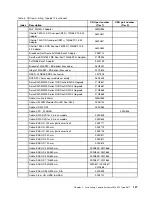
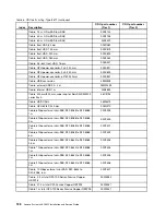
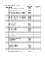
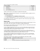
See Chapter 4 “Parts listing, Lenovo System x3650 M5 Type 8871” on page 113 to determine whether a
component is a structural part, consumable part, Tier 1 CRU, or Tier 2 CRU.
For information about the terms of the warranty, see the
Warranty Information
document that comes with
the server.
For more information about getting service and assistance, see Appendix D “Getting help and technical
assistance” on page 1307.
Returning a device or component
If you are instructed to return a device or component, follow all packaging instructions, and use any
packaging materials for shipping that are supplied to you.
Internal cable routing and connectors
This section provides information about routing the cables when you install some components in the server.
Note:
Disengage all latches, release tabs or locks on cable connectors when you disconnect all cables from
the system board. Failing to release them before removing the cables will damage the cable sockets on
the system board. The cable sockets on the system board are fragile. Any damage to the cable sockets
may require replacing the system board.
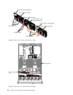
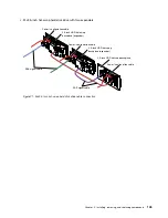
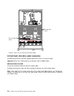
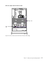
General cable routing connections
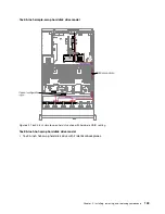
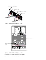
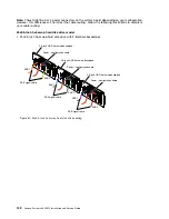
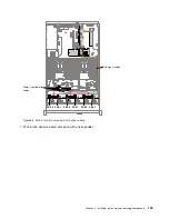
Cabling VGA power connector
The internal routing and connectors for the front USB and video cables.
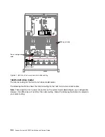
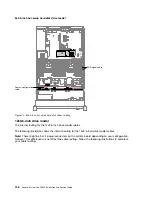
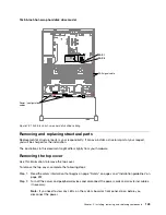
The following illustration shows the internal routing and connectors for the video graphic adapter (VGA)
power cables:
© Copyright Lenovo 2016, 2017
135
Содержание x3650 M5
Страница 1: ...Lenovo System x3650 M5 Installation and Service Guide Machine Type 8871 ...
Страница 47: ...Figure 35 System board switches jumpers and buttons Chapter 1 The System x3650 M5 server 35 ...
Страница 60: ...48 Lenovo System x3650 M5 Installation and Service Guide ...
Страница 80: ...68 Lenovo System x3650 M5 Installation and Service Guide ...
Страница 124: ...112 Lenovo System x3650 M5 Installation and Service Guide ...
Страница 146: ...134 Lenovo System x3650 M5 Installation and Service Guide ...
Страница 1322: ...1310 Lenovo System x3650 M5 Installation and Service Guide ...
Страница 1329: ...People s Republic of China Class A electronic emission statement Taiwan Class A compliance statement Appendix E Notices 1317 ...
Страница 1330: ...Taiwan BSMI RoHS declaration 1318 Lenovo System x3650 M5 Installation and Service Guide ...
Страница 1339: ......
Страница 1340: ......

