3: Installation
EMG™ Edge Management Gateway User Guide
43
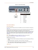
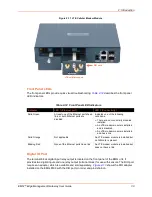
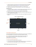
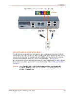
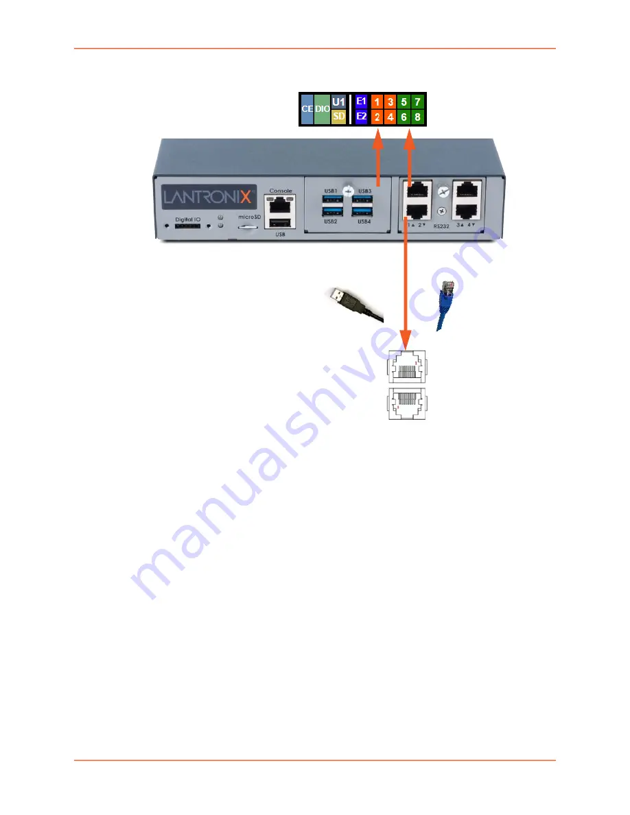
Figure 3-8 Sample Device Port Connections (Front Side)
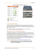
Modular Expansion for I/O Module Bays
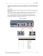
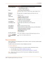
The EMG module configuration can be changed by adding or replacing I/O modules in the I/O
module bays. When populating the bays, Bay 1 and Bay 2 may be populated in any order and one
module may be left empty. The bays are ordered from left to right: Bay 1 is the slot next to the
console port and USB port and Bay 2 is the slot to the right of Bay 1. See
Any changes to the I/O modules must be done while the EMG unit is powered off.
shows
the available I/O module configurations. To install an I/O module, refer to
.
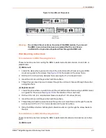
Warning:
The I/O module slots on the front of the EMG unit may only be used with
the RJ45 or USB I/O modules. Do not insert the connectivity modules on
the front of the EMG unit.
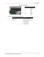
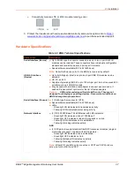
4-Port USB
I/O Module
4-Port RJ45
I/O Module
Bay 1 Bay 2
Dashboard
Содержание EMG 8500
Страница 1: ...Part Number PMD 00008 Revision A October 2019 EMG Edge Management Gateway User Guide EMG 8500 ...
Страница 69: ...6 Networking EMG Edge Management Gateway User Guide 69 Figure 6 2 Network Network Settings 2 of 2 ...
Страница 302: ...14 Maintenance EMG Edge Management Gateway User Guide 302 Figure 14 12 About EMG ...

