2: Introduction
EMG™ Edge Management Gateway User Guide
33
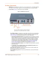
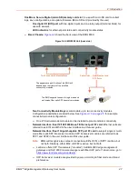
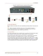
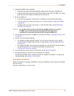
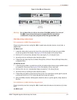
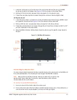
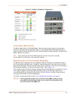
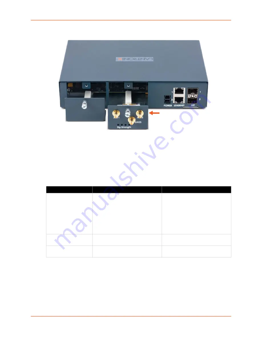
Figure 2-11 LTE Cellular Modem Module
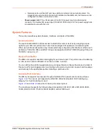
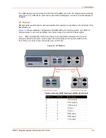
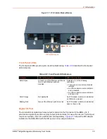
Front Panel LEDs
The front panel LEDs provide quick visual troubleshooting.
describes the front panel
LED indicators.
Table 2-12 Front Panel LED Indicators
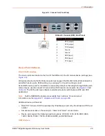
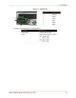
Digital IO Port
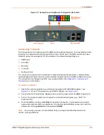
The terminal block digital input relay output is located on the front panel of the EMG unit. It
provides two digital inputs and one relay output (terminal block) for use with sensors. The DIO port
requires an adapter, which is available and sold separately.
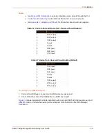
shows the DIO adapter
installed on the EMG 8500 with the DIO port pin order and pin definition.
Indicator
LED 1 (Ethernet port)
LED 2 (Connectivity)
Solid Green
At least one of the Ethernet ports has a
link, or both Ethernet ports are
disabled.
Indicates one of the following
conditions:
There are no connectivity modules
installed
An LTE modem module is installed
and is disabled
An LTE modem module is installed
and has a link
Solid Orange
Not applicable
An LTE modem module is installed but
no SIM card is present
Blinking Red
None of the Ethernet ports has a link. An LTE modem module is installed but
does not have a link.
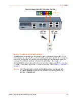
LTE cellular module
SIM card
Содержание EMG 8500
Страница 1: ...Part Number PMD 00008 Revision A October 2019 EMG Edge Management Gateway User Guide EMG 8500 ...
Страница 69: ...6 Networking EMG Edge Management Gateway User Guide 69 Figure 6 2 Network Network Settings 2 of 2 ...
Страница 302: ...14 Maintenance EMG Edge Management Gateway User Guide 302 Figure 14 12 About EMG ...

